HP Dl180 ProLiant DL180 Generation 5 Server Maintenance and Service Guide - Page 47
Remove cables attached to the system board from both sides of the cage.
 |
UPC - 883585990917
View all HP Dl180 manuals
Add to My Manuals
Save this manual to your list of manuals |
Page 47 highlights
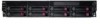
Figure 27 Removing the front drive cage (1) Figure 28 Removing the front drive cage (2) 1. Remove cables attached to the system board from both sides of the cage. (Figure 27) 2. Loosen the screws on both side of the front drive cage. (Figure 28) 3. Pull out the front drive cage from the chassis. Removal and replacement procedures 47
-
 1
1 -
2
-
3
-
4
-
5
-
6
-
7
-
8
-
9
-
10
-
11
-
12
-
13
-
14
-
15
-
16
-
17
-
18
-
19
-
20
-
21
-
22
-
23
-
24
-
25
-
26
-
27
-
28
-
29
-
30
-
31
-
32
-
33
-
34
-
35
-
36
-
37
-
38
-
39
-
40
-
41
-
 42
42 -
 43
43 -
 44
44 -
 45
45 -
 46
46 -
 47
47 -
 48
48 -
 49
49 -
 50
50 -
 51
51 -
 52
52 -
53
-
54
-
55
-
56
-
57
-
58
-
59
-
60
-
61
-
62
-
63
-
64
-
65
-
66
-
67
-
68
-
69
-
70
-
71
-
72
-
73
-
74
-
75
-
76
-
77
-
78
-
79
-
80
-
81
-
82
-
83
-
84
-
85
-
86
-
87
-
88
-
89
-
90
-
91
-
92
-
93
-
94
-
95
-
96
-
97
-
98
-
99
-
100
-
101
 |
 |

Removal and replacement procedures
47
Figure 27
Removing the front drive cage (1)
Figure 28
Removing the front drive cage (2)
1.
Remove cables attached to the system board from both sides of the cage. (Figure 27)
2.
Loosen the screws on both side of the front drive cage. (Figure 28)
3.
Pull out the front drive cage from the chassis.