HP Dl180 ProLiant DL180 Generation 5 Server Maintenance and Service Guide - Page 72
System board components, Designator, Description
 |
UPC - 883585990917
View all HP Dl180 manuals
Add to My Manuals
Save this manual to your list of manuals |
Page 72 highlights
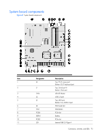
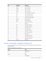
System board components Figure 67 System board components Item 1 2 3 4 5 6 7 8 9 10 11 Designator J3 J1 SW4 J2 J5 J8 SW1 PCIE4 XBTA1 PCIE5 J29 Description Top: PS/2 mouse port Bottom: PS/2 keyboard port Top: Serial port A Bottom: VGA port UID LED Button USB 2.0 port Top: LAN port Bottom: Two USB 2.0 port IPMI Card Slot NMI Button PCIe slot Battery PCIe slot Internal USB 2.0 Type A Connectors, switches, and LEDs 72
-
 1
1 -
2
-
3
-
4
-
5
-
6
-
7
-
8
-
9
-
10
-
11
-
12
-
13
-
14
-
15
-
16
-
17
-
18
-
19
-
20
-
21
-
22
-
23
-
24
-
25
-
26
-
27
-
28
-
29
-
30
-
31
-
32
-
33
-
34
-
35
-
36
-
37
-
38
-
39
-
40
-
41
-
42
-
43
-
44
-
45
-
46
-
47
-
48
-
49
-
50
-
51
-
52
-
53
-
54
-
55
-
56
-
57
-
58
-
59
-
60
-
61
-
62
-
63
-
64
-
65
-
66
-
 67
67 -
 68
68 -
 69
69 -
 70
70 -
 71
71 -
 72
72 -
 73
73 -
 74
74 -
 75
75 -
 76
76 -
 77
77 -
78
-
79
-
80
-
81
-
82
-
83
-
84
-
85
-
86
-
87
-
88
-
89
-
90
-
91
-
92
-
93
-
94
-
95
-
96
-
97
-
98
-
99
-
100
-
101
 |
 |

Connectors, switches, and LEDs
72
System board components
Figure 67
System board components
Item
Designator
Description
1
J3
Top: PS/2 mouse port
Bottom: PS/2 keyboard port
2
J1
Top: Serial port A
Bottom: VGA port
3
SW4
UID LED Button
4
J2
USB 2.0 port
5
J5
Top: LAN port
Bottom: Two USB 2.0 port
6
J8
IPMI Card Slot
7
SW1
NMI Button
8
PCIE4
PCIe slot
9
XBTA1
Battery
10
PCIE5
PCIe slot
11
J29
Internal USB 2.0 Type A