HP Dx9000 Service Reference Guide: HP dx9000 TouchSmart Business PC - Page 22
Stand assembly, Back cover
 |
UPC - 884420541578
View all HP Dx9000 manuals
Add to My Manuals
Save this manual to your list of manuals |
Page 22 highlights
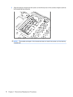
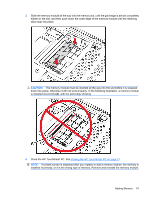
Stand assembly 1. Pull the stand up to a 90 degree position and push left on its latch to lock it in place. 2. Remove the memory cover. 3. Detach the four screws securing the stand to the computer. 4. Lift the stand off of the PC. To install the stand, reverse the removal procedures. Back cover 1. Remove the wireless keyboard and mouse receiver from its USB slot on the bottom edge of the system. 2. Remove the I/O cover and the I/O cable guide. 16 Chapter 3 Removal and Replacement Procedures
-
 1
1 -
2
-
3
-
4
-
5
-
6
-
7
-
8
-
9
-
10
-
11
-
12
-
13
-
14
-
15
-
16
-
 17
17 -
 18
18 -
 19
19 -
 20
20 -
 21
21 -
 22
22 -
 23
23 -
 24
24 -
 25
25 -
 26
26 -
 27
27 -
28
-
29
-
30
-
31
-
32
-
33
-
34
-
35
-
36
-
37
-
38
-
39
-
40
-
41
-
42
-
43
-
44
-
45
-
46
-
47
-
48
-
49
-
50
-
51
-
52
 |
 |
Stand assembly
1.
Pull the stand up to a 90 degree position and push left on its latch to lock it in place.
2.
Remove the memory cover.
3.
Detach the four screws securing the stand to the computer.
4.
Lift the stand off of the PC.
To install the stand, reverse the removal procedures.
Back cover
1.
Remove the wireless keyboard and mouse receiver from its USB slot on the bottom edge of the
system.
2.
Remove the I/O cover and the I/O cable guide.
16
Chapter 3
Removal and Replacement Procedures