HP Dx9000 Service Reference Guide: HP dx9000 TouchSmart Business PC - Page 24
Optical drive, Manually removing an optical disc
 |
UPC - 884420541578
View all HP Dx9000 manuals
Add to My Manuals
Save this manual to your list of manuals |
Page 24 highlights
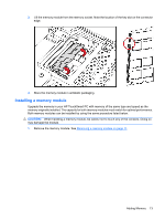
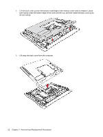
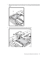
b. 3 screws in the I/O area c. 4 screws at the bottom of the back cover. 7. After removing all 9 screws, pull up on the bottom edge of the cover to release it from the PC. 8. Tilt the cover up and remove it from the PC To install the back cover, reverse the removal procedures. Optical drive Manually removing an optical disc NOTE: The optical drive may have a small pin hole on its front face; if it does not, manual ejection is not possible. 18 Chapter 3 Removal and Replacement Procedures
-
 1
1 -
2
-
3
-
4
-
5
-
6
-
7
-
8
-
9
-
10
-
11
-
12
-
13
-
14
-
15
-
16
-
17
-
18
-
 19
19 -
 20
20 -
 21
21 -
 22
22 -
 23
23 -
 24
24 -
 25
25 -
 26
26 -
 27
27 -
 28
28 -
 29
29 -
30
-
31
-
32
-
33
-
34
-
35
-
36
-
37
-
38
-
39
-
40
-
41
-
42
-
43
-
44
-
45
-
46
-
47
-
48
-
49
-
50
-
51
-
52
 |
 |
b.
3 screws in the I/O area
c.
4 screws at the bottom of the back cover.
7.
After removing all 9 screws, pull up on the bottom edge of the cover to release it from the PC.
8.
Tilt the cover up and remove it from the PC
To install the back cover, reverse the removal procedures.
Optical drive
Manually removing an optical disc
NOTE:
The optical drive may have a small pin hole on its front face; if it does not, manual ejection is
not possible.
18
Chapter 3
Removal and Replacement Procedures