HP Dx9000 Service Reference Guide: HP dx9000 TouchSmart Business PC - Page 23
screws are located near the optical disc drive, Back cover - mount
 |
UPC - 884420541578
View all HP Dx9000 manuals
Add to My Manuals
Save this manual to your list of manuals |
Page 23 highlights
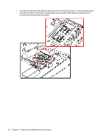
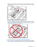
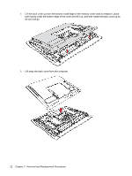
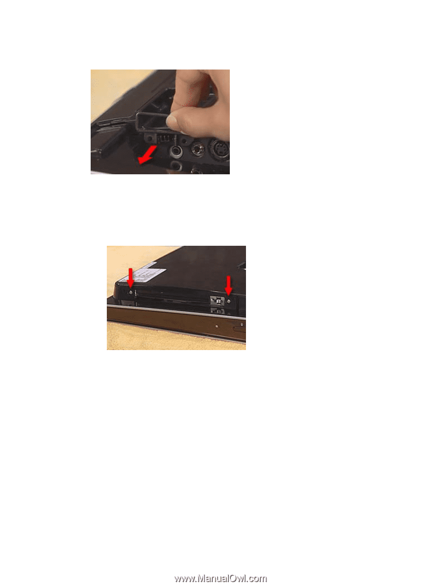
3. Remove the I/O cable guide. To remove it, first squeeze the tabs at its sides and then pull the guide off its mounting post. 4. Remove the memory door and the stand. 5. Remove the optical disc drive cover panel. 6. Remove the nine screws that secure the back cover to the computer, as follows: a. 2 screws are located near the optical disc drive Back cover 17
-
 1
1 -
2
-
3
-
4
-
5
-
6
-
7
-
8
-
9
-
10
-
11
-
12
-
13
-
14
-
15
-
16
-
17
-
 18
18 -
 19
19 -
 20
20 -
 21
21 -
 22
22 -
 23
23 -
 24
24 -
 25
25 -
 26
26 -
 27
27 -
 28
28 -
29
-
30
-
31
-
32
-
33
-
34
-
35
-
36
-
37
-
38
-
39
-
40
-
41
-
42
-
43
-
44
-
45
-
46
-
47
-
48
-
49
-
50
-
51
-
52
 |
 |
3.
Remove the I/O cable guide. To remove it, first squeeze the tabs at its sides and then pull the guide
off its mounting post.
4.
Remove the memory door and the stand.
5.
Remove the optical disc drive cover panel.
6.
Remove the nine screws that secure the back cover to the computer, as follows:
a.
2 screws are located near the optical disc drive
Back cover
17