HP ENVY 14-j100 Maintenance and Service Guide - Page 38
Removal and replacement procedures for Customer Self-Repair parts, Component replacement procedures
 |
View all HP ENVY 14-j100 manuals
Add to My Manuals
Save this manual to your list of manuals |
Page 38 highlights
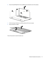
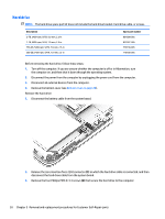
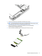
5 Removal and replacement procedures for Customer Self-Repair parts This chapter provides removal and replacement procedures for Customer Self-Repair parts. NOTE: The Customer Self-Repair program is not available in all locations. Installing a part not supported by the Customer Self-Repair program may void your warranty. Check your warranty to determine if Customer Self-Repair is supported in your location. HP continually improves and changes product parts. For complete and current information on supported parts for your computer, go to http://partsurfer.hp.com, select your country or region, and then follow the on-screen instructions. Component replacement procedures NOTE: Details about your computer, including model, serial number, product key, and length of warranty, are included on the service tag on the bottom of your computer. See Labels on page 14 for details. There may be as many as 21 screws that must be removed, replaced, and/or loosened when servicing Customer Self-Repair parts. Make special note of each screw size and location during removal and replacement. Bottom cover NOTE: The bottom cover spare kit includes shielding and speaker grilles. Description For use only on computer models equipped with a graphics subsystem with discrete memory For use only on computer models equipped with a graphics subsystem with UMA memory Spare part number 818100-001 818099-001 1. Turn off the computer. If you are unsure whether the computer is off or in Hibernation, turn the computer on, and then shut it down through the operating system. 2. Disconnect the power from the computer by unplugging the power cord from the computer. 3. Disconnect all external devices from the computer. Remove the bottom cover: 1. Remove the rear rubber foot strip (1). The rear rubber foot strip is included in the Rubber Kit, spare part number 818126-001. 2. Remove the four Phillips PM2.5×5.7 screws (2) that secure the bottom cover to the computer. 28 Chapter 5 Removal and replacement procedures for Customer Self-Repair parts
-
 1
1 -
2
-
3
-
4
-
5
-
6
-
7
-
8
-
9
-
10
-
11
-
12
-
13
-
14
-
15
-
16
-
17
-
18
-
19
-
20
-
21
-
22
-
23
-
24
-
25
-
26
-
27
-
28
-
29
-
30
-
31
-
32
-
 33
33 -
 34
34 -
 35
35 -
 36
36 -
 37
37 -
 38
38 -
 39
39 -
 40
40 -
 41
41 -
 42
42 -
 43
43 -
44
-
45
-
46
-
47
-
48
-
49
-
50
-
51
-
52
-
53
-
54
-
55
-
56
-
57
-
58
-
59
-
60
-
61
-
62
-
63
-
64
-
65
-
66
-
67
-
68
-
69
-
70
-
71
-
72
-
73
-
74
-
75
-
76
-
77
-
78
-
79
-
80
-
81
-
82
-
83
-
84
-
85
-
86
-
87
-
88
-
89
-
90
-
91
-
92
-
93
-
94
-
95
-
96
-
97
-
98
-
99
-
100
-
101
-
102
-
103
-
104
-
105
-
106
-
107
-
108
-
109
-
110
-
111
-
112
-
113
-
114
-
115
-
116
 |
 |