HP ENVY 14-j100 Maintenance and Service Guide - Page 60
Remove the RJ45 cover, Reverse this procedure to install the RJ45 cover.
 |
View all HP ENVY 14-j100 manuals
Add to My Manuals
Save this manual to your list of manuals |
Page 60 highlights
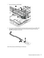
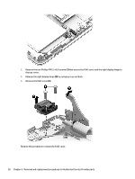
2. Remove the two Phillips PM2.5×8.8 screws (1) that secure the RJ45 cover and the right display hinge to the top cover. 3. Release the right display hinge (2) by swinging it up and back. 4. Remove the RJ45 cover (3). Reverse this procedure to install the RJ45 cover. 50 Chapter 6 Removal and replacement procedures for Authorized Service Provider parts
-
 1
1 -
2
-
3
-
4
-
5
-
6
-
7
-
8
-
9
-
10
-
11
-
12
-
13
-
14
-
15
-
16
-
17
-
18
-
19
-
20
-
21
-
22
-
23
-
24
-
25
-
26
-
27
-
28
-
29
-
30
-
31
-
32
-
33
-
34
-
35
-
36
-
37
-
38
-
39
-
40
-
41
-
42
-
43
-
44
-
45
-
46
-
47
-
48
-
49
-
50
-
51
-
52
-
53
-
54
-
 55
55 -
 56
56 -
 57
57 -
 58
58 -
 59
59 -
 60
60 -
 61
61 -
 62
62 -
 63
63 -
 64
64 -
 65
65 -
66
-
67
-
68
-
69
-
70
-
71
-
72
-
73
-
74
-
75
-
76
-
77
-
78
-
79
-
80
-
81
-
82
-
83
-
84
-
85
-
86
-
87
-
88
-
89
-
90
-
91
-
92
-
93
-
94
-
95
-
96
-
97
-
98
-
99
-
100
-
101
-
102
-
103
-
104
-
105
-
106
-
107
-
108
-
109
-
110
-
111
-
112
-
113
-
114
-
115
-
116
 |
 |
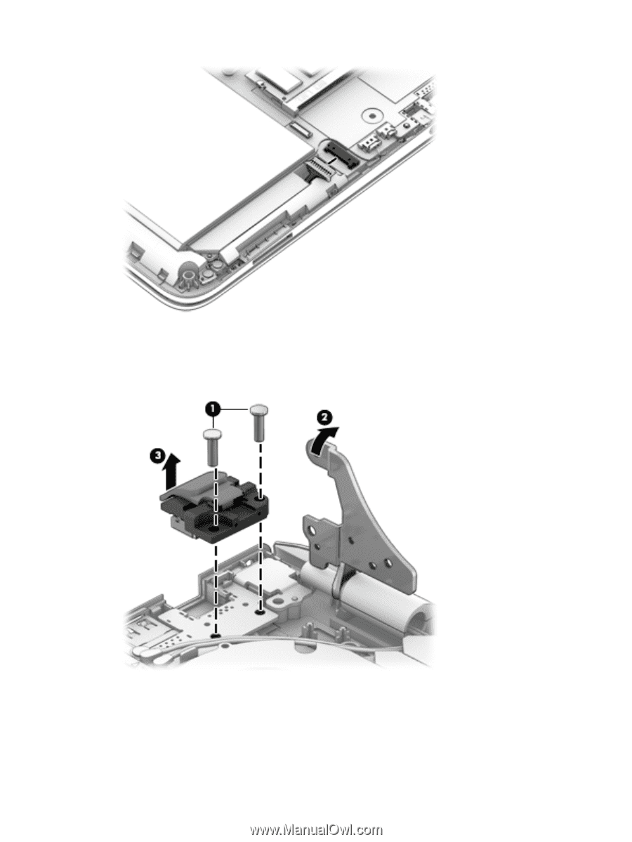
2.
Remove the two Phillips PM2.5×8.8 screws
(1)
that secure the RJ45 cover and the right display hinge to
the top
cover.
3.
Release the right display hinge
(2)
by swinging it up and back.
4.
Remove the RJ45 cover
(3)
.
Reverse this procedure to install the RJ45 cover.
50
Chapter 6
Removal and replacement procedures for Authorized Service Provider parts