HP ENVY 14-j100 Maintenance and Service Guide - Page 67
and system board components, it may be necessary to move the heat sink from side to side to detach it.
 |
View all HP ENVY 14-j100 manuals
Add to My Manuals
Save this manual to your list of manuals |
Page 67 highlights
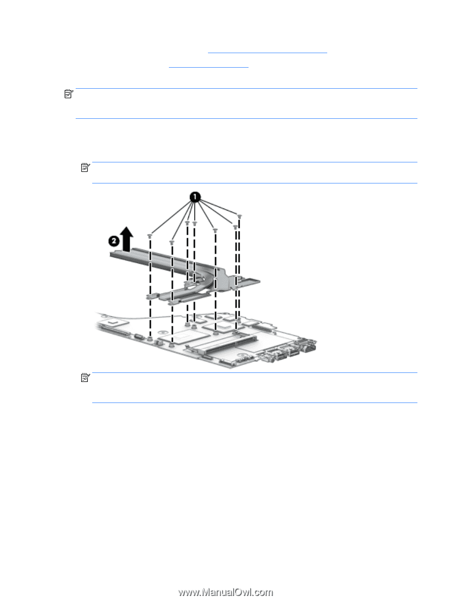
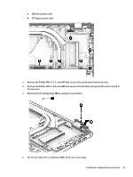
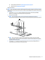
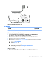
d. Security cable slot bracket (see Security cable slot bracket on page 51) e. System board (see System board on page 52) Remove the heat sink: NOTE: Steps 1 and 2 apply to computer models equipped with a graphics subsystem with discrete memory. See steps 3 and 4 for heat sink removal steps for computer models equipped with a graphics subsystem with UMA memory. 1. Following the 1, 2, 3, 4, 5, 6, 7 sequence stamped into the heat sink, remove the seven Phillips PM2.0×3.3 screws (1) that secure the heat sink to the system board. 2. Remove the heat sink (2). NOTE: Due to the adhesive quality of the thermal material located between the heat sink and system board components, it may be necessary to move the heat sink from side to side to detach it. NOTE: Steps 3 and 4 apply to computer models equipped with a graphics subsystem with UMA memory. See steps 1 and 2 for heat sink removal steps for computer models equipped with a graphics subsystem with discrete memory. 3. Following the 1, 2, 3, 4 sequence stamped into the heat sink, remove the four Phillips PM2.0×3.3 screws (1) that secure the heat sink to the system board. Component replacement procedures 57
-
 1
1 -
2
-
3
-
4
-
5
-
6
-
7
-
8
-
9
-
10
-
11
-
12
-
13
-
14
-
15
-
16
-
17
-
18
-
19
-
20
-
21
-
22
-
23
-
24
-
25
-
26
-
27
-
28
-
29
-
30
-
31
-
32
-
33
-
34
-
35
-
36
-
37
-
38
-
39
-
40
-
41
-
42
-
43
-
44
-
45
-
46
-
47
-
48
-
49
-
50
-
51
-
52
-
53
-
54
-
55
-
56
-
57
-
58
-
59
-
60
-
61
-
 62
62 -
 63
63 -
 64
64 -
 65
65 -
 66
66 -
 67
67 -
 68
68 -
 69
69 -
 70
70 -
 71
71 -
 72
72 -
73
-
74
-
75
-
76
-
77
-
78
-
79
-
80
-
81
-
82
-
83
-
84
-
85
-
86
-
87
-
88
-
89
-
90
-
91
-
92
-
93
-
94
-
95
-
96
-
97
-
98
-
99
-
100
-
101
-
102
-
103
-
104
-
105
-
106
-
107
-
108
-
109
-
110
-
111
-
112
-
113
-
114
-
115
-
116
 |
 |