HP ENVY 14-j100 Maintenance and Service Guide - Page 71
Power connector cable, Before removing the power connector cable, follow these steps
 |
View all HP ENVY 14-j100 manuals
Add to My Manuals
Save this manual to your list of manuals |
Page 71 highlights
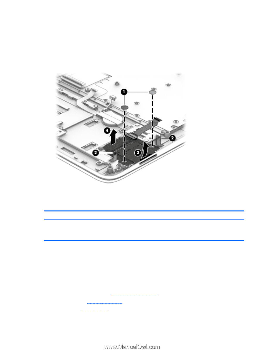
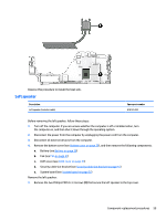
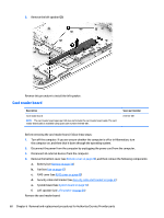
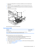
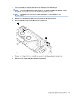
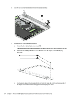
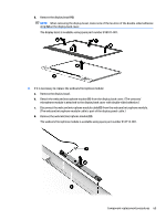
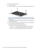
1. Remove the two Phillips PM2.0×2.2 broad head screws (1) that secure the card reader board to the top cover. 2. Release the two pieces of grounding tape (2) that secure the card reader board to the top cover. 3. Release the card reader board (3) from the opening in the top cover by lifting it up and away from the top cover. 4. Remove the card reader board (4). Reverse this procedure to install the card reader board. Power connector cable Description Power connector cable NOTE: The power connector cable spare part kit does not include the power connector cable bracket. The power connector cable bracket is available using spare part number 818117-001. Spare part number 818108-001 Before removing the power connector cable, follow these steps: 1. Turn off the computer. If you are unsure whether the computer is off or in Hibernation, turn the computer on, and then shut it down through the operating system. 2. Disconnect the power from the computer by unplugging the power cord from the computer. 3. Disconnect all external devices from the computer. 4. Remove the bottom cover (see Bottom cover on page 28), and then remove the following components: a. Battery (see Battery on page 38) b. Fan (see Fan on page 47) Component replacement procedures 61
-
 1
1 -
2
-
3
-
4
-
5
-
6
-
7
-
8
-
9
-
10
-
11
-
12
-
13
-
14
-
15
-
16
-
17
-
18
-
19
-
20
-
21
-
22
-
23
-
24
-
25
-
26
-
27
-
28
-
29
-
30
-
31
-
32
-
33
-
34
-
35
-
36
-
37
-
38
-
39
-
40
-
41
-
42
-
43
-
44
-
45
-
46
-
47
-
48
-
49
-
50
-
51
-
52
-
53
-
54
-
55
-
56
-
57
-
58
-
59
-
60
-
61
-
62
-
63
-
64
-
65
-
 66
66 -
 67
67 -
 68
68 -
 69
69 -
 70
70 -
 71
71 -
 72
72 -
 73
73 -
 74
74 -
 75
75 -
 76
76 -
77
-
78
-
79
-
80
-
81
-
82
-
83
-
84
-
85
-
86
-
87
-
88
-
89
-
90
-
91
-
92
-
93
-
94
-
95
-
96
-
97
-
98
-
99
-
100
-
101
-
102
-
103
-
104
-
105
-
106
-
107
-
108
-
109
-
110
-
111
-
112
-
113
-
114
-
115
-
116
 |
 |