HP ENVY 14-j100 Maintenance and Service Guide - Page 79
If it is necessary to replace the wireless antenna cables and transceivers
 |
View all HP ENVY 14-j100 manuals
Add to My Manuals
Save this manual to your list of manuals |
Page 79 highlights
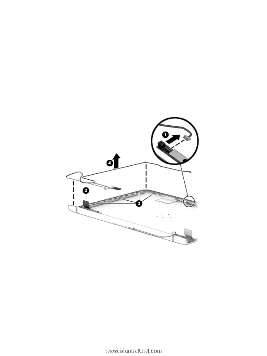
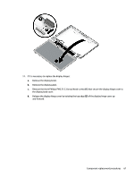
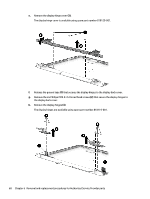
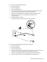
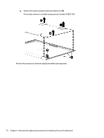
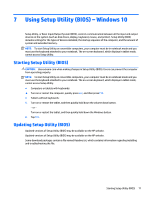
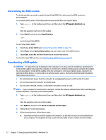
11. If it is necessary to replace the display panel cable: a. Remove the display bezel. b. Remove the display panel. c. Remove the display hingecover. d. Disconnect the webcam/microphone module cable (1) from the webcam/microphone module. (The webcam/microphone module cable is part of the display panel cable.) e. Release the ground tape (2) that secures the display panel cable to the display back cover. f. Release the display panel cable from theclips (3) and routing channel built into the display back cover. g. Remove the display panel cable (4). The display panel cable is available using spare part number 818104-001. 12. If it is necessary to replace the wireless antenna cables and transceivers: a. Remove the display bezel. b. Remove the display panel. c. Remove the display hingecover. d. Release the wireless antenna transceivers (1) from the display back cover. (The wireless antenna transceivers are attached to the display back cover with double-sided adhesive.) e. Release the ground tape (2) that secures the display panel cable to the display back cover. f. Release the wireless antenna cable from theclips (3) built into the display back cover. Component replacement procedures 69
-
 1
1 -
2
-
3
-
4
-
5
-
6
-
7
-
8
-
9
-
10
-
11
-
12
-
13
-
14
-
15
-
16
-
17
-
18
-
19
-
20
-
21
-
22
-
23
-
24
-
25
-
26
-
27
-
28
-
29
-
30
-
31
-
32
-
33
-
34
-
35
-
36
-
37
-
38
-
39
-
40
-
41
-
42
-
43
-
44
-
45
-
46
-
47
-
48
-
49
-
50
-
51
-
52
-
53
-
54
-
55
-
56
-
57
-
58
-
59
-
60
-
61
-
62
-
63
-
64
-
65
-
66
-
67
-
68
-
69
-
70
-
71
-
72
-
73
-
 74
74 -
 75
75 -
 76
76 -
 77
77 -
 78
78 -
 79
79 -
 80
80 -
 81
81 -
 82
82 -
 83
83 -
 84
84 -
85
-
86
-
87
-
88
-
89
-
90
-
91
-
92
-
93
-
94
-
95
-
96
-
97
-
98
-
99
-
100
-
101
-
102
-
103
-
104
-
105
-
106
-
107
-
108
-
109
-
110
-
111
-
112
-
113
-
114
-
115
-
116
 |
 |