HP ENVY 14-j100 Maintenance and Service Guide - Page 73
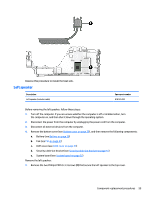
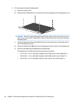
from the system board., that secures the left display hinge to the top cover.
 |
View all HP ENVY 14-j100 manuals
Add to My Manuals
Save this manual to your list of manuals |
Page 73 highlights
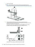
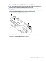
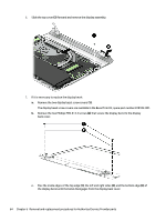
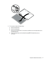
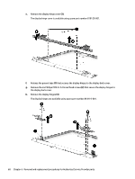
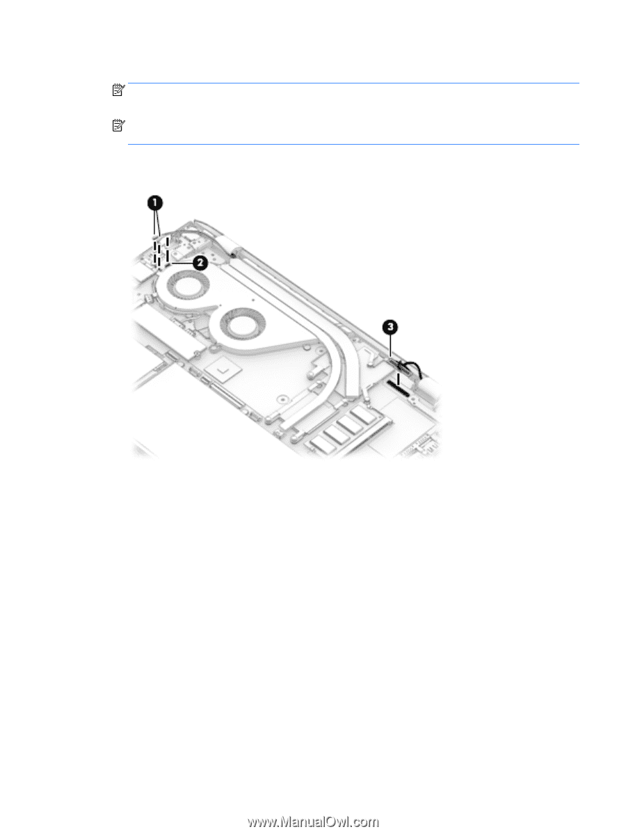
1. Disconnect the WLAN antenna cables (1) from the terminals on the WLAN module. NOTE: The #1/white WLAN antenna cable connects to the WLAN module #1/Main terminal. The #2/ black WLAN antenna cable connects to the WLAN module #2/Aux terminal. NOTE: Step 2 applies only to computer models equipped with a graphics subystem with discrete memory. 2. Release the wireless antenna cables from the retention clip (2) built into the fan. 3. Disconnect the display panel cable (3) from the system board. 4. Remove the Phillips PM2.5×8.8 screw (1) that secures the left display hinge to the top cover. 5. Release the left display hinge (2) by swinging it up and back. Component replacement procedures 63
-
 1
1 -
2
-
3
-
4
-
5
-
6
-
7
-
8
-
9
-
10
-
11
-
12
-
13
-
14
-
15
-
16
-
17
-
18
-
19
-
20
-
21
-
22
-
23
-
24
-
25
-
26
-
27
-
28
-
29
-
30
-
31
-
32
-
33
-
34
-
35
-
36
-
37
-
38
-
39
-
40
-
41
-
42
-
43
-
44
-
45
-
46
-
47
-
48
-
49
-
50
-
51
-
52
-
53
-
54
-
55
-
56
-
57
-
58
-
59
-
60
-
61
-
62
-
63
-
64
-
65
-
66
-
67
-
 68
68 -
 69
69 -
 70
70 -
 71
71 -
 72
72 -
 73
73 -
 74
74 -
 75
75 -
 76
76 -
 77
77 -
 78
78 -
79
-
80
-
81
-
82
-
83
-
84
-
85
-
86
-
87
-
88
-
89
-
90
-
91
-
92
-
93
-
94
-
95
-
96
-
97
-
98
-
99
-
100
-
101
-
102
-
103
-
104
-
105
-
106
-
107
-
108
-
109
-
110
-
111
-
112
-
113
-
114
-
115
-
116
 |
 |
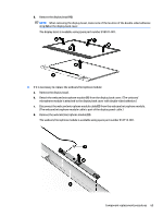
1.
Disconnect the WLAN antenna cables
(1)
from the terminals on the WLAN module.
NOTE:
The #1/white WLAN antenna cable connects to the WLAN module #1/Main terminal. The #2/
black WLAN antenna cable connects to the WLAN module #2/Aux terminal.
NOTE:
Step 2 applies only to computer models equipped with a graphics subystem with
discrete memory.
2.
Release the wireless antenna cables from the retention clip
(2)
built into the fan.
3.
Disconnect the display panel cable
(3)
from the system board.
4.
Remove the Phillips PM2.5×8.8 screw
(1)
that secures the left display hinge to the top cover.
5.
Release the left display hinge
(2)
by swinging it up and back.
Component replacement procedures
63