HP ENVY 14-j100 Maintenance and Service Guide - Page 43
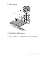
the system board. The WLAN module tilts up., Remove the WLAN module
 |
View all HP ENVY 14-j100 manuals
Add to My Manuals
Save this manual to your list of manuals |
Page 43 highlights
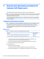
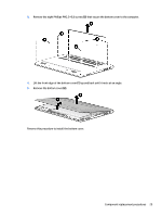
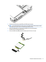
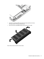
2. Disconnect the WLAN antenna cables (1) from the WLAN module terminals. NOTE: The #1/white WLAN antenna cable connects to the WLAN module #1/Main terminal. The #2/ black WLAN antenna cable connects to the WLAN module #2/Aux terminal. 3. Remove the Phillips PM2.0×3.7 broad head screw (2) that secures the WLAN module to the system board. (The WLAN module tilts up.) 4. Remove the WLAN module (3) by pulling the module away from the slot at an angle. Component replacement procedures 33
-
 1
1 -
2
-
3
-
4
-
5
-
6
-
7
-
8
-
9
-
10
-
11
-
12
-
13
-
14
-
15
-
16
-
17
-
18
-
19
-
20
-
21
-
22
-
23
-
24
-
25
-
26
-
27
-
28
-
29
-
30
-
31
-
32
-
33
-
34
-
35
-
36
-
37
-
 38
38 -
 39
39 -
 40
40 -
 41
41 -
 42
42 -
 43
43 -
 44
44 -
 45
45 -
 46
46 -
 47
47 -
 48
48 -
49
-
50
-
51
-
52
-
53
-
54
-
55
-
56
-
57
-
58
-
59
-
60
-
61
-
62
-
63
-
64
-
65
-
66
-
67
-
68
-
69
-
70
-
71
-
72
-
73
-
74
-
75
-
76
-
77
-
78
-
79
-
80
-
81
-
82
-
83
-
84
-
85
-
86
-
87
-
88
-
89
-
90
-
91
-
92
-
93
-
94
-
95
-
96
-
97
-
98
-
99
-
100
-
101
-
102
-
103
-
104
-
105
-
106
-
107
-
108
-
109
-
110
-
111
-
112
-
113
-
114
-
115
-
116
 |
 |
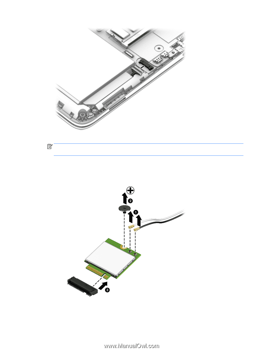
2.
Disconnect the WLAN antenna cables
(1)
from the WLAN module terminals.
NOTE:
The #1/white WLAN antenna cable connects to the WLAN module #1/Main terminal. The #2/
black WLAN antenna cable connects to the WLAN module #2/Aux terminal.
3.
Remove the Phillips PM2.0×3.7 broad head screw
(2)
that secures the WLAN module to
the system board. (The WLAN module tilts up.)
4.
Remove the WLAN module
(3)
by pulling the module away from the slot at an angle.
Component replacement procedures
33