HP Elite 8300 HP Compaq Business PC Hardware Reference Guide - Elite 8300 Seri - Page 104
HP Elite 8300 Manual
 |
View all HP Elite 8300 manuals
Add to My Manuals
Save this manual to your list of manuals |
Page 104 highlights
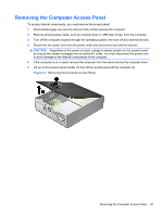
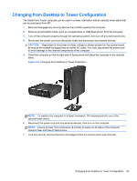
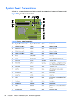
System Board Connections Refer to the following illustration and table to identify the system board connectors for your model. Figure 4-7 System Board Connections Table 4-1 System Board Connections No. System Board Connector System Board Label Color 1 DIMM4 (Channel A) DIMM4 white 2 DIMM3 (Channel A) DIMM3 black 3 DIMM2 (Channel B) DIMM2 white 4 DIMM1 (Channel B) DIMM1 black 5 Power SATAPWR1 black 6 Power SATAPWR0 black 7 SATA 3.0 SATA0 dark blue 8 SATA 3.0 SATA1 light blue 9 SATA 2.0 10 eSATA SATA2 ESATA white black 11 Parallel Port 12 Serial Port 13 USB PAR COMB MEDIA black black black 14 Hood Lock 15 Hood Sensor 16 USB HLCK HSENSE MEDIA2 black white black 17 PCI Express x1 X1PCIEXP1 black Component Memory Module Memory Module Memory Module Memory Module (unused) SATA Optical and Hard Drives 1st Hard Drive 2nd Hard Drive, or 2nd Optical Drive if an ESATA Adapter Cable exists 1st Optical Drive eSATA Adapter Cable, or 2nd Optical Drive Parallel Port Serial Port USB Device, such as a Media Card Reader Hood Lock Hood Sensor USB Device, such as a Media Card Reader Expansion Card 96 Chapter 4 Small Form Factor (SFF) Hardware Upgrades
-
 1
1 -
2
-
3
-
4
-
5
-
6
-
7
-
8
-
9
-
10
-
11
-
12
-
13
-
14
-
15
-
16
-
17
-
18
-
19
-
20
-
21
-
22
-
23
-
24
-
25
-
26
-
27
-
28
-
29
-
30
-
31
-
32
-
33
-
34
-
35
-
36
-
37
-
38
-
39
-
40
-
41
-
42
-
43
-
44
-
45
-
46
-
47
-
48
-
49
-
50
-
51
-
52
-
53
-
54
-
55
-
56
-
57
-
58
-
59
-
60
-
61
-
62
-
63
-
64
-
65
-
66
-
67
-
68
-
69
-
70
-
71
-
72
-
73
-
74
-
75
-
76
-
77
-
78
-
79
-
80
-
81
-
82
-
83
-
84
-
85
-
86
-
87
-
88
-
89
-
90
-
91
-
92
-
93
-
94
-
95
-
96
-
97
-
98
-
 99
99 -
 100
100 -
 101
101 -
 102
102 -
 103
103 -
 104
104 -
 105
105 -
 106
106 -
 107
107 -
 108
108 -
 109
109 -
110
-
111
-
112
-
113
-
114
-
115
-
116
-
117
-
118
-
119
-
120
-
121
-
122
-
123
-
124
-
125
-
126
-
127
-
128
-
129
-
130
-
131
-
132
-
133
-
134
-
135
-
136
-
137
-
138
-
139
-
140
-
141
-
142
-
143
-
144
-
145
-
146
-
147
-
148
-
149
-
150
-
151
-
152
-
153
-
154
-
155
-
156
-
157
-
158
-
159
-
160
-
161
-
162
-
163
-
164
-
165
-
166
-
167
-
168
-
169
-
170
-
171
-
172
-
173
-
174
-
175
-
176
-
177
-
178
-
179
 |
 |
