HP Elite 8300 HP Compaq Business PC Hardware Reference Guide - Elite 8300 Seri - Page 45
Installing Drives
 |
View all HP Elite 8300 manuals
Add to My Manuals
Save this manual to your list of manuals |
Page 45 highlights
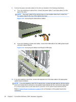
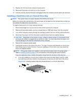
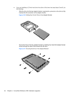
Installing Drives When installing drives, follow these guidelines: ● The primary Serial ATA (SATA) hard drive must be connected to the dark blue SATA connector on the system board labeled SATA0. If you are adding a second hard drive, connect it to the light blue SATA1 connector. ● Connect the first SATA optical drive to the white SATA connector on the system board labeled SATA2. If you are adding a second optical drive, connect it to the white SATA3 connector. ● Connect an optional eSATA adapter cable to the black SATA connector on the system board labeled ESATA. ● Connect a media card reader USB cable to the USB connector on the system board labeled MEDIA. ● The power cable for the SATA optical drives is a two-headed cable this is plugged into the system board with the first connector routed to the middle 5.25-inch bay and the second connector routed to the top 5.25-inch bay. ● The power cable for the SATA hard drives is a three-headed cable this is plugged into the system board with the first connector routed to the bottom 3.5-inch bay, the second connector routed to the middle 3.5-inch bay, and the third connector routed to the top 3.5-inch bay. ● The system does not support Parallel ATA (PATA) optical drives or PATA hard drives. ● You must install guide screws to ensure the drive will line up correctly in the drive cage and lock in place. HP has provided extra guide screws installed on the chassis. The hard drive uses 6-32 isolation mounting guide screws in the lower two bays and standard 6-32 screws in the upper bay. Four of each are installed on the hard drive bracket under the access panel. All other drives use M3 metric screws, eight of which are installed on the optical drive bracket under the access panel. The HP-supplied metric guide screws are black. The HP-supplied 6-32 isolation mounting guide screws are silver and blue. The HP-supplied standard 6-32 screws are silver. If you are replacing the primary hard drive, you must remove the four silver and blue 6-32 isolation mounting guide screws from the old hard drive and install them in the new hard drive. Figure 2-21 Extra Guide Screw Locations Installing Drives 37
-
 1
1 -
2
-
3
-
4
-
5
-
6
-
7
-
8
-
9
-
10
-
11
-
12
-
13
-
14
-
15
-
16
-
17
-
18
-
19
-
20
-
21
-
22
-
23
-
24
-
25
-
26
-
27
-
28
-
29
-
30
-
31
-
32
-
33
-
34
-
35
-
36
-
37
-
38
-
39
-
 40
40 -
 41
41 -
 42
42 -
 43
43 -
 44
44 -
 45
45 -
 46
46 -
 47
47 -
 48
48 -
 49
49 -
 50
50 -
51
-
52
-
53
-
54
-
55
-
56
-
57
-
58
-
59
-
60
-
61
-
62
-
63
-
64
-
65
-
66
-
67
-
68
-
69
-
70
-
71
-
72
-
73
-
74
-
75
-
76
-
77
-
78
-
79
-
80
-
81
-
82
-
83
-
84
-
85
-
86
-
87
-
88
-
89
-
90
-
91
-
92
-
93
-
94
-
95
-
96
-
97
-
98
-
99
-
100
-
101
-
102
-
103
-
104
-
105
-
106
-
107
-
108
-
109
-
110
-
111
-
112
-
113
-
114
-
115
-
116
-
117
-
118
-
119
-
120
-
121
-
122
-
123
-
124
-
125
-
126
-
127
-
128
-
129
-
130
-
131
-
132
-
133
-
134
-
135
-
136
-
137
-
138
-
139
-
140
-
141
-
142
-
143
-
144
-
145
-
146
-
147
-
148
-
149
-
150
-
151
-
152
-
153
-
154
-
155
-
156
-
157
-
158
-
159
-
160
-
161
-
162
-
163
-
164
-
165
-
166
-
167
-
168
-
169
-
170
-
171
-
172
-
173
-
174
-
175
-
176
-
177
-
178
-
179
 |
 |
