HP Elite 8300 HP Compaq Business PC Hardware Reference Guide - Elite 8300 Seri - Page 119
CAUTION, Installing Guide Screws in the Optical Drive
 |
View all HP Elite 8300 manuals
Add to My Manuals
Save this manual to your list of manuals |
Page 119 highlights
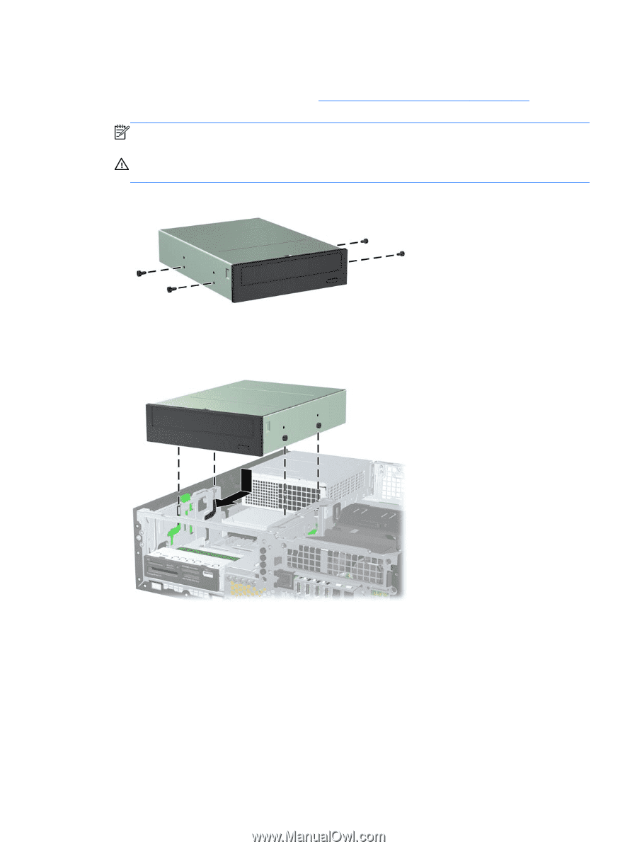
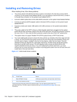
8. Install four M3 metric guide screws in the lower holes on each side of the drive. HP has provided four extra M3 metric guide screws on the front of the chassis, under the front bezel. The M3 metric guide screws are black. Refer to Installing and Removing Drives on page 106 for an illustration of the extra M3 metric guide screws location. NOTE: When replacing the drive, transfer the four M3 metric guide screws from the old drive to the new one. CAUTION: Use only 5-mm long screws as guide screws. Longer screws can damage the internal components of the drive. Figure 4-22 Installing Guide Screws in the Optical Drive 9. Position the guide screws on the drive into the J-slots in the drive bay. Then slide the drive toward the front of the computer until it locks into place. Figure 4-23 Installing the Optical Drive Installing and Removing Drives 111
-
 1
1 -
2
-
3
-
4
-
5
-
6
-
7
-
8
-
9
-
10
-
11
-
12
-
13
-
14
-
15
-
16
-
17
-
18
-
19
-
20
-
21
-
22
-
23
-
24
-
25
-
26
-
27
-
28
-
29
-
30
-
31
-
32
-
33
-
34
-
35
-
36
-
37
-
38
-
39
-
40
-
41
-
42
-
43
-
44
-
45
-
46
-
47
-
48
-
49
-
50
-
51
-
52
-
53
-
54
-
55
-
56
-
57
-
58
-
59
-
60
-
61
-
62
-
63
-
64
-
65
-
66
-
67
-
68
-
69
-
70
-
71
-
72
-
73
-
74
-
75
-
76
-
77
-
78
-
79
-
80
-
81
-
82
-
83
-
84
-
85
-
86
-
87
-
88
-
89
-
90
-
91
-
92
-
93
-
94
-
95
-
96
-
97
-
98
-
99
-
100
-
101
-
102
-
103
-
104
-
105
-
106
-
107
-
108
-
109
-
110
-
111
-
112
-
113
-
 114
114 -
 115
115 -
 116
116 -
 117
117 -
 118
118 -
 119
119 -
 120
120 -
 121
121 -
 122
122 -
 123
123 -
 124
124 -
125
-
126
-
127
-
128
-
129
-
130
-
131
-
132
-
133
-
134
-
135
-
136
-
137
-
138
-
139
-
140
-
141
-
142
-
143
-
144
-
145
-
146
-
147
-
148
-
149
-
150
-
151
-
152
-
153
-
154
-
155
-
156
-
157
-
158
-
159
-
160
-
161
-
162
-
163
-
164
-
165
-
166
-
167
-
168
-
169
-
170
-
171
-
172
-
173
-
174
-
175
-
176
-
177
-
178
-
179
 |
 |