HP LD4245tm Network Sign Manager User Guide - Page 32
Group, Tile ID, s are numbered from the upper-left corner of the matrix
 |
View all HP LD4245tm manuals
Add to My Manuals
Save this manual to your list of manuals |
Page 32 highlights
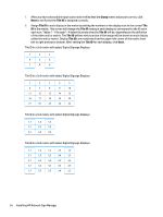
7. After you have selected the input source and verified that the Group matrix values are correct, click Next to verify that the Tile ID is assigned correctly. 8. Assign Tile ID to each display in the matrix by setting the numbers in the display icon to the correct Tile ID in the matrix. This screen will change the Tile ID setting in each display to correspond to the ID set in each icon. Tables 1-1 through 1-4 below illustrate what the Tile ID will be, depending on the definition of the video wall or matrix. The Tile ID defines which portion of the image will be shown on each display within the wall or matrix. Display Tile IDs are numbered from the upper-left corner of the matrix from left to right and top to bottom. After setting the Tile ID for each display, click Next. Tile ID in a 3x3 matrix with select Digital Signage Displays 1 2 3 4 5 6 7 8 9 Tile ID in a 5x5 matrix with select Digital Signage Displays 1 2 3 4 5 6 7 8 9 10 11 12 13 14 15 16 17 18 19 20 21 22 23 24 25 Tile ID in a 3x3 matrix with select Digital Signage Displays 1,1 1,2 1,3 2.1 2,2 2,3 3,1 3,2 3,3 Tile ID in a 5x5 matrix with select Digital Signage Displays 1,1 1,2 1,3 1,4 1,5 2.1 2,2 2,3 2,4 2,5 3,1 3,2 3,3 3,4 3,5 4,1 4,2 4,3 4,4 4,5 5,1 5,2 5,3 5,4 5,5 26 Installing HP Network Sign Manager
-
 1
1 -
2
-
3
-
4
-
5
-
6
-
7
-
8
-
9
-
10
-
11
-
12
-
13
-
14
-
15
-
16
-
17
-
18
-
19
-
20
-
21
-
22
-
23
-
24
-
25
-
26
-
 27
27 -
 28
28 -
 29
29 -
 30
30 -
 31
31 -
 32
32 -
 33
33 -
 34
34 -
 35
35 -
 36
36 -
 37
37 -
38
-
39
-
40
-
41
 |
 |
