HP Pavilion 17-g000 17-g099 AMD Models - Maintenance and Service Guide - Page 46
Remove the Phillips PM2.0×3.0 screw
 |
View all HP Pavilion 17-g000 manuals
Add to My Manuals
Save this manual to your list of manuals |
Page 46 highlights
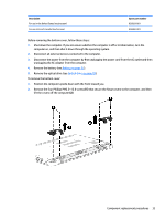
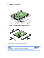
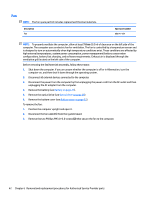
Description Broadcom BCM43142 802.11 b/g/n 1x1 Wi-Fi + Bluetooth 4.0 M.2 Combo Adapter Intel Dual Band Wireless-AC 3165 802.11 ac 1x1 WiFi + Bluetooth 4.0 Combo Adapter Spare part number 792608-005 806723-005 CAUTION: To prevent an unresponsive system, replace the wireless module only with a wireless module authorized for use in the computer by the governmental agency that regulates wireless devices in your country or region. If you replace the module and then receive a warning message, remove the module to restore device functionality, and then contact support. Before removing the WLAN module, follow these steps: 1. Shut down the computer. If you are unsure whether the computer is off or in Hibernation, turn the computer on, and then shut it down through the operating system. 2. Disconnect all external devices connected to the computer. 3. Disconnect the power from the computer by first unplugging the power cord from the AC outlet and then unplugging the AC adapter from the computer. 4. Remove the battery (see Battery on page 27). 5. Remove the optical drive (see Optical drive on page 28). 6. Remove the bottom cover (see Bottom cover on page 32). To remove the WLAN module: 1. Disconnect the WLAN antenna cables (1) from the terminals on the WLAN module. NOTE: The #1 WLAN antenna cable is connected to the WLAN module Main terminal. The #2 WLAN antenna cable is connected to the WLAN module Aux terminal. 2. Remove the Phillips PM2.0×3.0 screw (2) that secures the WLAN module to the system board. (The WLAN module tilts up.) 38 Chapter 6 Removal and replacement procedures for Authorized Service Provider parts
-
 1
1 -
2
-
3
-
4
-
5
-
6
-
7
-
8
-
9
-
10
-
11
-
12
-
13
-
14
-
15
-
16
-
17
-
18
-
19
-
20
-
21
-
22
-
23
-
24
-
25
-
26
-
27
-
28
-
29
-
30
-
31
-
32
-
33
-
34
-
35
-
36
-
37
-
38
-
39
-
40
-
 41
41 -
 42
42 -
 43
43 -
 44
44 -
 45
45 -
 46
46 -
 47
47 -
 48
48 -
 49
49 -
 50
50 -
 51
51 -
52
-
53
-
54
-
55
-
56
-
57
-
58
-
59
-
60
-
61
-
62
-
63
-
64
-
65
-
66
-
67
-
68
-
69
-
70
-
71
-
72
-
73
-
74
-
75
-
76
-
77
-
78
-
79
-
80
-
81
-
82
-
83
-
84
-
85
-
86
-
87
-
88
-
89
-
90
-
91
-
92
-
93
-
94
-
95
-
96
-
97
-
98
-
99
-
100
-
101
-
102
-
103
-
104
-
105
-
106
-
107
-
108
-
109
-
110
-
111
-
112
-
113
-
114
-
115
-
116
-
117
-
118
-
119
-
120
 |
 |