HP Pavilion 17-g000 17-g099 AMD Models - Maintenance and Service Guide - Page 55
Optical drive connector, Position the computer upright.
 |
View all HP Pavilion 17-g000 manuals
Add to My Manuals
Save this manual to your list of manuals |
Page 55 highlights
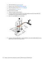
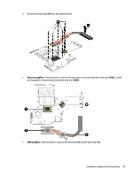
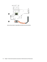
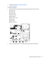
Optical drive connector Description Optical drive connector (included in the power connector kit) Spare part number 810928-001 Before removing the optical drive connector, follow these steps: 1. Shut down the computer. If you are unsure whether the computer is off or in Hibernation, turn the computer on, and then shut it down through the operating system. 2. Disconnect all external devices connected to the computer. 3. Disconnect the power from the computer by first unplugging the power cord from the AC outlet and then unplugging the AC adapter from the computer. 4. Remove the battery (see Battery on page 27). 5. Remove the optical drive (see Optical drive on page 28). 6. Remove the bottom cover (see Bottom cover on page 32). To remove the optical drive connector: 1. Position the computer upright. 2. Disconnect the optical drive connector cable from the system board (1). 3. Remove the two Phillips PM2.5×3.0 screws (2) that secure the optical drive connector to the computer. 4. Remove the optical drive connector and cable (3). Reverse this procedure to install the optical drive connector. Component replacement procedures 47
-
 1
1 -
2
-
3
-
4
-
5
-
6
-
7
-
8
-
9
-
10
-
11
-
12
-
13
-
14
-
15
-
16
-
17
-
18
-
19
-
20
-
21
-
22
-
23
-
24
-
25
-
26
-
27
-
28
-
29
-
30
-
31
-
32
-
33
-
34
-
35
-
36
-
37
-
38
-
39
-
40
-
41
-
42
-
43
-
44
-
45
-
46
-
47
-
48
-
49
-
 50
50 -
 51
51 -
 52
52 -
 53
53 -
 54
54 -
 55
55 -
 56
56 -
 57
57 -
 58
58 -
 59
59 -
 60
60 -
61
-
62
-
63
-
64
-
65
-
66
-
67
-
68
-
69
-
70
-
71
-
72
-
73
-
74
-
75
-
76
-
77
-
78
-
79
-
80
-
81
-
82
-
83
-
84
-
85
-
86
-
87
-
88
-
89
-
90
-
91
-
92
-
93
-
94
-
95
-
96
-
97
-
98
-
99
-
100
-
101
-
102
-
103
-
104
-
105
-
106
-
107
-
108
-
109
-
110
-
111
-
112
-
113
-
114
-
115
-
116
-
117
-
118
-
119
-
120
 |
 |