HP Pavilion 17-g000 17-g099 AMD Models - Maintenance and Service Guide - Page 52
that secure the heat sink to the system board., If you have a model with discrete graphics
 |
View all HP Pavilion 17-g000 manuals
Add to My Manuals
Save this manual to your list of manuals |
Page 52 highlights
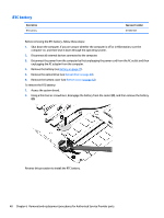
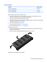
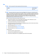
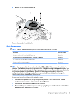
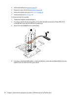
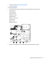
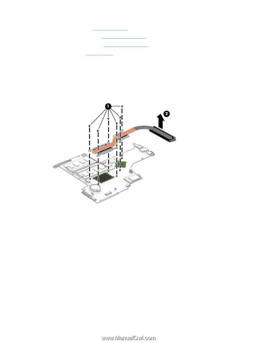
4. Remove the battery (see Battery on page 27). 5. Remove the optical drive (see Optical drive on page 28). 6. Remove the bottom cover (see Bottom cover on page 32). 7. Remove the fan (see Fan on page 42). To remove the heat sink assembly: 1. Position the computer upright and open it.. 2. If you have a model with discrete graphics, In the order indicated, remove the six Phillips PM2.0×3.0 screws (1) that secure the heat sink to the system board. 3. Remove the heat sink (2) from the system board. 4. If you have a model with UMA graphics, In the order indicated, remove the six Phillips PM2.0×3.0 screws (1) that secure the heat sink to the system board. 44 Chapter 6 Removal and replacement procedures for Authorized Service Provider parts
-
 1
1 -
2
-
3
-
4
-
5
-
6
-
7
-
8
-
9
-
10
-
11
-
12
-
13
-
14
-
15
-
16
-
17
-
18
-
19
-
20
-
21
-
22
-
23
-
24
-
25
-
26
-
27
-
28
-
29
-
30
-
31
-
32
-
33
-
34
-
35
-
36
-
37
-
38
-
39
-
40
-
41
-
42
-
43
-
44
-
45
-
46
-
 47
47 -
 48
48 -
 49
49 -
 50
50 -
 51
51 -
 52
52 -
 53
53 -
 54
54 -
 55
55 -
 56
56 -
 57
57 -
58
-
59
-
60
-
61
-
62
-
63
-
64
-
65
-
66
-
67
-
68
-
69
-
70
-
71
-
72
-
73
-
74
-
75
-
76
-
77
-
78
-
79
-
80
-
81
-
82
-
83
-
84
-
85
-
86
-
87
-
88
-
89
-
90
-
91
-
92
-
93
-
94
-
95
-
96
-
97
-
98
-
99
-
100
-
101
-
102
-
103
-
104
-
105
-
106
-
107
-
108
-
109
-
110
-
111
-
112
-
113
-
114
-
115
-
116
-
117
-
118
-
119
-
120
 |
 |
4.
Remove the battery (see
Battery
on page
27
).
5.
Remove the optical drive (see
Optical drive
on page
28
).
6.
Remove the bottom cover (see
Bottom cover
on page
32
).
7.
Remove the fan (see
Fan
on page
42
).
To remove the heat sink assembly:
1.
Position the computer upright and open it..
2.
If you have a model with discrete graphics, In the order indicated, remove the six Phillips PM2.0×3.0
screws
(1)
that secure the heat sink to the system board.
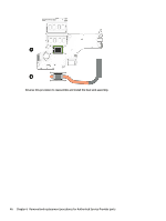
3.
Remove the heat sink
(2)
from the system board.
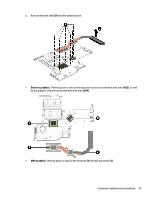
4.
If you have a model with UMA graphics, In the order indicated, remove the six Phillips PM2.0×3.0 screws
(1)
that secure the heat sink to the system board.
44
Chapter 6
Removal and replacement procedures for Authorized Service Provider parts