HP Pavilion 17-g000 17-g099 AMD Models - Maintenance and Service Guide - Page 70
Display assembly, touch
 |
View all HP Pavilion 17-g000 manuals
Add to My Manuals
Save this manual to your list of manuals |
Page 70 highlights
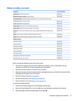
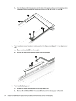
Display assembly, touch Component Display bezel (includes screw covers) Touch screen connector board spared with the display panel Webcam/microphone module touch screen Raw display panel (16:9 Ultra Wide Aspect Ratio [43.9-cm 17.3-in]; includes screw covers) Antiglare HD+ touch screen Antiglare FHD+ touch screen Panel Bracket (included with the Display Panel touch screen) Display cable FHD touch screen (includes screw covers) Display cable HD touch screen (includes screw covers) Antennas touch screen (includes wireless antenna cables and transceivers; includes screw covers) Hinges touch screen (left and right, includes screw covers) Display enclosure: Cobalt blue models touch screen Sunset red models touch screen Blizzard white models touch screen Natural silver models touch screen Violet purple models touch screen Peachy pink models touch screen Sparkling black models for use with touch screen Pale gold models for use with touch screen Spare part number 809291-001 810961-001 809300-001 809301-001 809294-001 809932-001 809272-001 809299-001 809281-001 809280-001 809284-001 809279-001 809283-001 809282-001 810948-001 836857-001 Before removing the display assembly, follow these steps: 1. Shut down the computer. If you are unsure whether the computer is off or in Hibernation, turn the computer on, and then shut it down through the operating system. 2. Disconnect all external devices connected to the computer. 3. Disconnect the power from the computer by first unplugging the power cord from the AC outlet and then unplugging the AC adapter from the computer. 4. Remove the battery (see Battery on page 27). 5. Remove the optical drive (see Optical drive on page 28). 6. Remove the bottom cover (see Bottom cover on page 32). To remove the display assembly: 1. Position the computer on its side, partially open. 2. Remove the four Phillips PM2.5×5.0 screws (1) that secure the display assembly to the computer. 62 Chapter 6 Removal and replacement procedures for Authorized Service Provider parts
-
 1
1 -
2
-
3
-
4
-
5
-
6
-
7
-
8
-
9
-
10
-
11
-
12
-
13
-
14
-
15
-
16
-
17
-
18
-
19
-
20
-
21
-
22
-
23
-
24
-
25
-
26
-
27
-
28
-
29
-
30
-
31
-
32
-
33
-
34
-
35
-
36
-
37
-
38
-
39
-
40
-
41
-
42
-
43
-
44
-
45
-
46
-
47
-
48
-
49
-
50
-
51
-
52
-
53
-
54
-
55
-
56
-
57
-
58
-
59
-
60
-
61
-
62
-
63
-
64
-
 65
65 -
 66
66 -
 67
67 -
 68
68 -
 69
69 -
 70
70 -
 71
71 -
 72
72 -
 73
73 -
 74
74 -
 75
75 -
76
-
77
-
78
-
79
-
80
-
81
-
82
-
83
-
84
-
85
-
86
-
87
-
88
-
89
-
90
-
91
-
92
-
93
-
94
-
95
-
96
-
97
-
98
-
99
-
100
-
101
-
102
-
103
-
104
-
105
-
106
-
107
-
108
-
109
-
110
-
111
-
112
-
113
-
114
-
115
-
116
-
117
-
118
-
119
-
120
 |
 |