HP Pavilion 17-g000 17-g099 AMD Models - Maintenance and Service Guide - Page 69
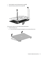
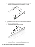
If replacing the display enclosure, be sure that the subcomponents including the webcam/microphone
 |
View all HP Pavilion 17-g000 manuals
Add to My Manuals
Save this manual to your list of manuals |
Page 69 highlights
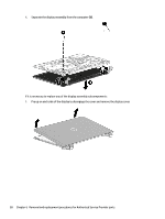
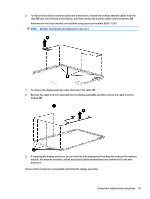
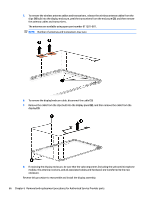
3. To remove the wireless antenna cables and transceivers, release the wireless antenna cables from the clips (1) built into the back of the display, and then remove the antenna cables and transceivers (2). Antennas for non-touch models are available using spare part number 809271-001. NOTE: Number of antennas and transceivers may vary. 4. To remove the display/webcam cable, disconnect the cable (1). 5. Remove the cable from the clips built into the display panel (2), and then remove the cable from the display (3). 6. If replacing the display enclosure, be sure that the subcomponents (including the webcam/microphone module, the antenna receivers, and all associated cables and hardware) are transferred to the new enclosure. Reverse this procedure to reassemble and install the display assembly. Component replacement procedures 61
-
 1
1 -
2
-
3
-
4
-
5
-
6
-
7
-
8
-
9
-
10
-
11
-
12
-
13
-
14
-
15
-
16
-
17
-
18
-
19
-
20
-
21
-
22
-
23
-
24
-
25
-
26
-
27
-
28
-
29
-
30
-
31
-
32
-
33
-
34
-
35
-
36
-
37
-
38
-
39
-
40
-
41
-
42
-
43
-
44
-
45
-
46
-
47
-
48
-
49
-
50
-
51
-
52
-
53
-
54
-
55
-
56
-
57
-
58
-
59
-
60
-
61
-
62
-
63
-
 64
64 -
 65
65 -
 66
66 -
 67
67 -
 68
68 -
 69
69 -
 70
70 -
 71
71 -
 72
72 -
 73
73 -
 74
74 -
75
-
76
-
77
-
78
-
79
-
80
-
81
-
82
-
83
-
84
-
85
-
86
-
87
-
88
-
89
-
90
-
91
-
92
-
93
-
94
-
95
-
96
-
97
-
98
-
99
-
100
-
101
-
102
-
103
-
104
-
105
-
106
-
107
-
108
-
109
-
110
-
111
-
112
-
113
-
114
-
115
-
116
-
117
-
118
-
119
-
120
 |
 |
