HP Pavilion 17-g000 17-g099 AMD Models - Maintenance and Service Guide - Page 56
System board, Remove the fan see
 |
View all HP Pavilion 17-g000 manuals
Add to My Manuals
Save this manual to your list of manuals |
Page 56 highlights
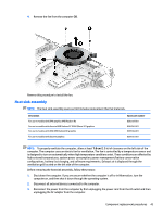
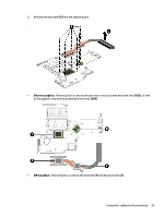
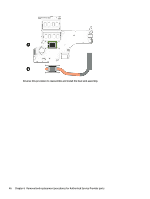
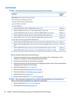
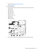
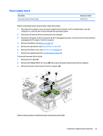
System board NOTE: The system board spare part kit includes replacement thermal materials. Description Spare part number System board (includes replacement thermal materials): All system boards use the following part numbers: xxxxxx-001: Without the Windows operating system xxxxxx-501: Windows 8.1 Standard xxxxxx-601: Windows 10 ● AMD A4-6210 UMA LVDS (1.8 GHz), 1600 MHz/2 MB L2, quad core 15 W ● AMD A6-6310 UMA LVDS (1.8 GHz, up to 2.4 GHz), 1600 MHz/2 MB L2, quad core 15 W 809397-xxx 809398-xxx ● AMD A8-7410 UMA LVDS (2.2 GHz, SC turbo up to 2.5 GHz), Max 1600 MHz/2 MB L2, quad core 15 W 809399-xxx ● AMD A10-8700P LVDS (1.8 GHz, SC turbo up to 3.2 GHz), Max1600 MHz/2 MB L2, quad core 15 W 809400-xxx ● AMD A10-8700P (1.8 GHz, SC turbo up to 3.2 GHz), Max1600 MHz/2 MB L2, quad core 15 W eDP 809402-xxx For use in models with discrete graphics (AMD R7 M360 (Meso-XT)): ● AMD A8-7410 discrete R7M360 LVDS (2.2 GHz, SC turbo up to 2.5 GHz), Max 1600 MHz/2 GB L2, quad core 15 W 809401-xxx ● AMD A8-7410 discrete R7M360 LVDS (2.2 GHz, SC turbo up to 2.5 GHz), Max 1600 MHz/2 GB L2, quad core 15 W 810937-xxx eDP ● AMD A10-8700P R7M360 (1.8 GHz, SC turbo up to 3.2 GHz), Max1600 MHz/2 MB L2, quad core 15 W eDP ● AMD A10-8700P R7M360 (1.8 GHz, SC turbo up to 3.2 GHz), Max1600 MHz/2 MB L2, quad core 15 W LVDS 809403-xxx 810936-xxx Before removing the system board, follow these steps: 1. Shut down the computer. If you are unsure whether the computer is off or in Hibernation, turn the computer on, and then shut it down through the operating system. 2. Disconnect all external devices connected to the computer. 3. Disconnect the power from the computer by first unplugging the power cord from the AC outlet and then unplugging the AC adapter from the computer. 4. Remove the battery (see Battery on page 27). 5. Remove the optical drive (see Optical drive on page 28). 6. Remove the bottom cover (see Bottom cover on page 32). 7. Remove the fan (see Fan on page 42). 8. Remove the heat sink (see Heat sink assembly on page 43). NOTE: When replacing the system board, be sure that the following components are removed from the defective system board and installed on the replacement system board: ● Memory modules (see Memory module on page 41) ● WLAN module (see WLAN module on page 37) 48 Chapter 6 Removal and replacement procedures for Authorized Service Provider parts
-
 1
1 -
2
-
3
-
4
-
5
-
6
-
7
-
8
-
9
-
10
-
11
-
12
-
13
-
14
-
15
-
16
-
17
-
18
-
19
-
20
-
21
-
22
-
23
-
24
-
25
-
26
-
27
-
28
-
29
-
30
-
31
-
32
-
33
-
34
-
35
-
36
-
37
-
38
-
39
-
40
-
41
-
42
-
43
-
44
-
45
-
46
-
47
-
48
-
49
-
50
-
 51
51 -
 52
52 -
 53
53 -
 54
54 -
 55
55 -
 56
56 -
 57
57 -
 58
58 -
 59
59 -
 60
60 -
 61
61 -
62
-
63
-
64
-
65
-
66
-
67
-
68
-
69
-
70
-
71
-
72
-
73
-
74
-
75
-
76
-
77
-
78
-
79
-
80
-
81
-
82
-
83
-
84
-
85
-
86
-
87
-
88
-
89
-
90
-
91
-
92
-
93
-
94
-
95
-
96
-
97
-
98
-
99
-
100
-
101
-
102
-
103
-
104
-
105
-
106
-
107
-
108
-
109
-
110
-
111
-
112
-
113
-
114
-
115
-
116
-
117
-
118
-
119
-
120
 |
 |