HP Pavilion HDX9575LA HP Pavilion HDX Entertainment Notebook PC - Maintenance - Page 50
Remove the camera module. The camera module is available using spare part number
 |
View all HP Pavilion HDX9575LA manuals
Add to My Manuals
Save this manual to your list of manuals |
Page 50 highlights
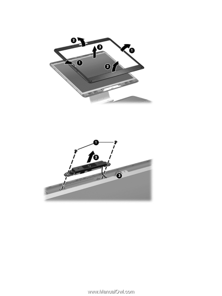
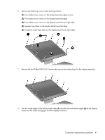
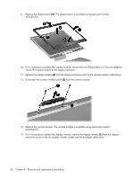
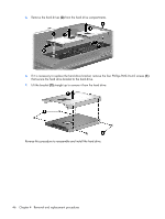
9. Remove the display bezel (3). The display bezel is available using spare part number 452307-001. 10. If it is necessary to replace the camera module, remove the two Phillips PM2.5×5.0 screws (1) that secure the camera module to the display enclosure. 11. Release the camera module (2) from the display enclosure as far as the camera module cable allows. 12. Disconnect the camera module cable (3) from the camera module. 13. Remove the camera module. The camera module is available using spare part number 452304-001. 14. If it is necessary to replace the display inverter, remove the display inverter (1) from the display enclosure as far as the two display inverter cables and the backlight cable allow. 42 Chapter 4 Removal and replacement procedures
-
 1
1 -
2
-
3
-
4
-
5
-
6
-
7
-
8
-
9
-
10
-
11
-
12
-
13
-
14
-
15
-
16
-
17
-
18
-
19
-
20
-
21
-
22
-
23
-
24
-
25
-
26
-
27
-
28
-
29
-
30
-
31
-
32
-
33
-
34
-
35
-
36
-
37
-
38
-
39
-
40
-
41
-
42
-
43
-
44
-
 45
45 -
 46
46 -
 47
47 -
 48
48 -
 49
49 -
 50
50 -
 51
51 -
 52
52 -
 53
53 -
 54
54 -
 55
55 -
56
-
57
-
58
-
59
-
60
-
61
-
62
-
63
-
64
-
65
-
66
-
67
-
68
-
69
-
70
-
71
-
72
-
73
-
74
-
75
-
76
-
77
-
78
-
79
-
80
-
81
-
82
-
83
-
84
-
85
-
86
-
87
-
88
-
89
-
90
-
91
-
92
-
93
-
94
-
95
-
96
-
97
-
98
-
99
-
100
-
101
-
102
-
103
-
104
-
105
-
106
-
107
-
108
-
109
-
110
-
111
-
112
-
113
-
114
-
115
-
116
-
117
-
118
-
119
-
120
-
121
-
122
-
123
-
124
-
125
-
126
-
127
-
128
-
129
-
130
-
131
-
132
-
133
-
134
-
135
-
136
-
137
-
138
-
139
-
140
-
141
-
142
-
143
-
144
-
145
-
146
-
147
-
148
-
149
-
150
-
151
-
152
-
153
-
154
-
155
-
156
-
157
-
158
-
159
-
160
-
161
-
162
-
163
 |
 |