HP Pavilion HDX9575LA HP Pavilion HDX Entertainment Notebook PC - Maintenance - Page 63
to which the keyboard cable is attached and, Release the zero insertion force ZIF connector
 |
View all HP Pavilion HDX9575LA manuals
Add to My Manuals
Save this manual to your list of manuals |
Page 63 highlights
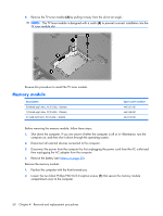
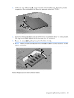
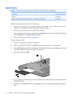
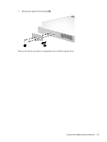
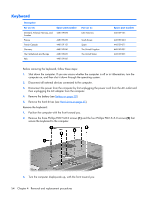
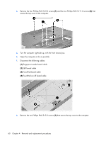
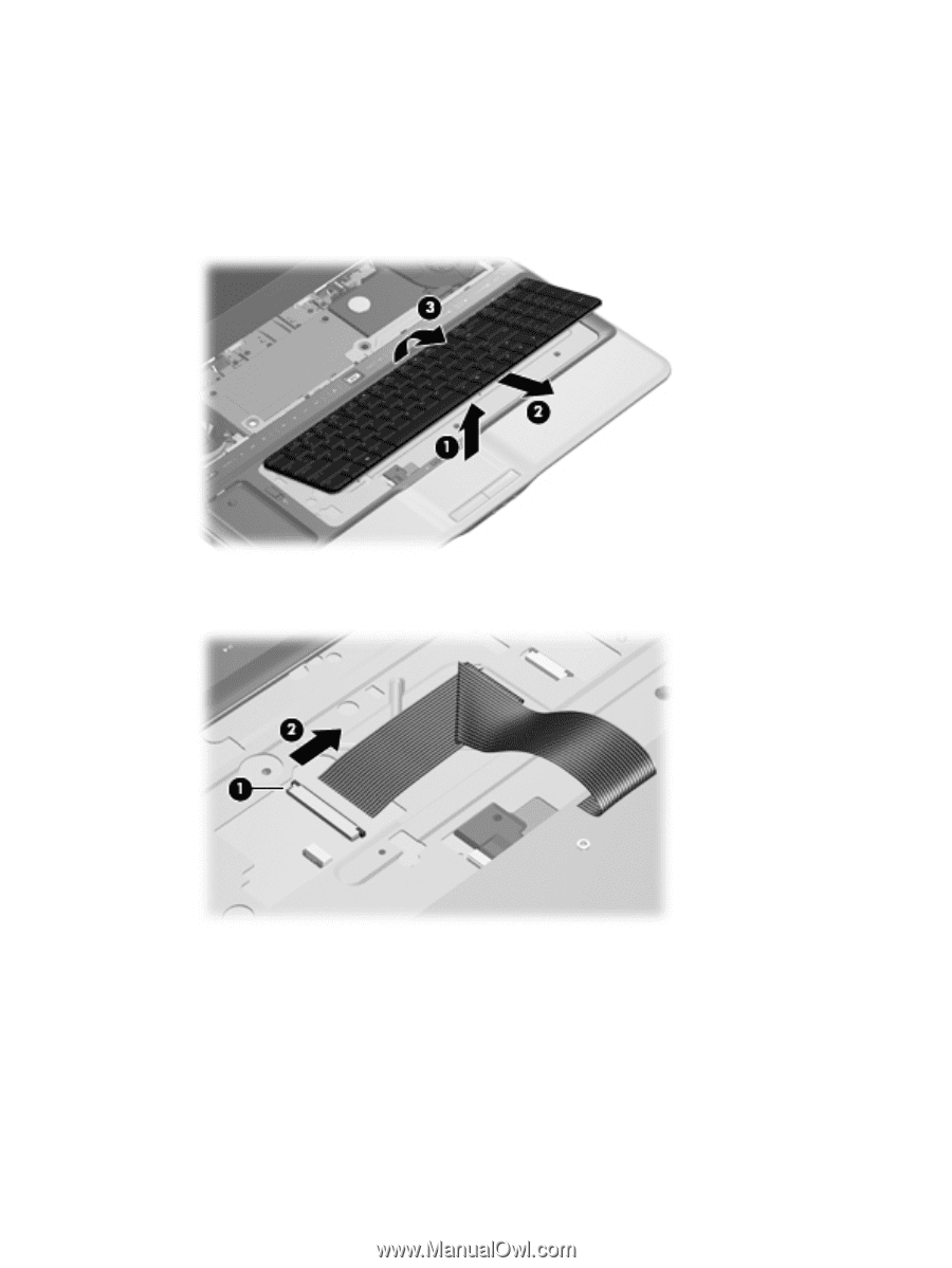
4. Open the computer as far as possible. 5. Lift the front edge of the keyboard (1) until it rests at an angle. 6. Slide the keyboard (2) forward until the tabs on the rear edge of the keyboard disengage from the slots in the top cover. 7. Rotate the rear edge of the keyboard (3) forward until it rests upside down on the palm rest. 8. Release the zero insertion force (ZIF) connector (1) to which the keyboard cable is attached and disconnect the keyboard cable (2). 9. Remove the keyboard. Reverse this procedure to install the keyboard. Component replacement procedures 55
-
 1
1 -
2
-
3
-
4
-
5
-
6
-
7
-
8
-
9
-
10
-
11
-
12
-
13
-
14
-
15
-
16
-
17
-
18
-
19
-
20
-
21
-
22
-
23
-
24
-
25
-
26
-
27
-
28
-
29
-
30
-
31
-
32
-
33
-
34
-
35
-
36
-
37
-
38
-
39
-
40
-
41
-
42
-
43
-
44
-
45
-
46
-
47
-
48
-
49
-
50
-
51
-
52
-
53
-
54
-
55
-
56
-
57
-
 58
58 -
 59
59 -
 60
60 -
 61
61 -
 62
62 -
 63
63 -
 64
64 -
 65
65 -
 66
66 -
 67
67 -
 68
68 -
69
-
70
-
71
-
72
-
73
-
74
-
75
-
76
-
77
-
78
-
79
-
80
-
81
-
82
-
83
-
84
-
85
-
86
-
87
-
88
-
89
-
90
-
91
-
92
-
93
-
94
-
95
-
96
-
97
-
98
-
99
-
100
-
101
-
102
-
103
-
104
-
105
-
106
-
107
-
108
-
109
-
110
-
111
-
112
-
113
-
114
-
115
-
116
-
117
-
118
-
119
-
120
-
121
-
122
-
123
-
124
-
125
-
126
-
127
-
128
-
129
-
130
-
131
-
132
-
133
-
134
-
135
-
136
-
137
-
138
-
139
-
140
-
141
-
142
-
143
-
144
-
145
-
146
-
147
-
148
-
149
-
150
-
151
-
152
-
153
-
154
-
155
-
156
-
157
-
158
-
159
-
160
-
161
-
162
-
163
 |
 |
4
.
Open the computer as far as possible.
5
.
Lift the front edge of the keyboard
(1)
until it rests at an angle.
6
.
Slide the keyboard
(2)
forward until the tabs on the rear edge of the keyboard disengage from the
slots in the top cover.
7
.
Rotate the rear edge of the keyboard
(3)
forward until it rests upside down on the palm rest.
8
.
Release the zero insertion force (ZIF) connector
(1)
to which the keyboard cable is attached and
disconnect the keyboard cable
(2)
.
9
.
Remove the keyboard.
Reverse this procedure to install the keyboard.
Component replacement procedures
55