HP Pavilion HDX9575LA HP Pavilion HDX Entertainment Notebook PC - Maintenance - Page 74
CAUTION, If it is necessary to replace any of the display assembly internal components, see
 |
View all HP Pavilion HDX9575LA manuals
Add to My Manuals
Save this manual to your list of manuals |
Page 74 highlights
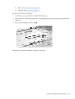
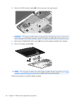
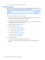
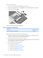
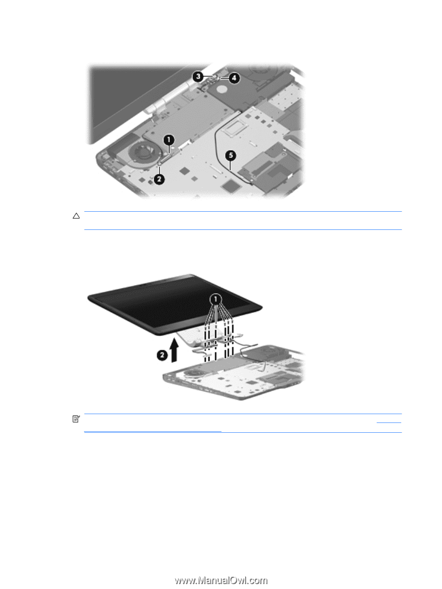
6. Remove the WLAN antenna cables (5) from the opening in the system board. CAUTION: The display assembly will be unsupported when the following screws are removed. To prevent damage to the display assembly, support the display assembly before removing the screws. 7. Remove the six Phillips PM3.0×8.0 screws (1) that secure the display assembly to the computer. 8. Remove the display assembly (2). NOTE: If it is necessary to replace any of the display assembly internal components, see Display assembly internal components on page 40 for display bezel removal information. Reverse this procedure to install the display assembly. 66 Chapter 4 Removal and replacement procedures
-
 1
1 -
2
-
3
-
4
-
5
-
6
-
7
-
8
-
9
-
10
-
11
-
12
-
13
-
14
-
15
-
16
-
17
-
18
-
19
-
20
-
21
-
22
-
23
-
24
-
25
-
26
-
27
-
28
-
29
-
30
-
31
-
32
-
33
-
34
-
35
-
36
-
37
-
38
-
39
-
40
-
41
-
42
-
43
-
44
-
45
-
46
-
47
-
48
-
49
-
50
-
51
-
52
-
53
-
54
-
55
-
56
-
57
-
58
-
59
-
60
-
61
-
62
-
63
-
64
-
65
-
66
-
67
-
68
-
 69
69 -
 70
70 -
 71
71 -
 72
72 -
 73
73 -
 74
74 -
 75
75 -
 76
76 -
 77
77 -
 78
78 -
 79
79 -
80
-
81
-
82
-
83
-
84
-
85
-
86
-
87
-
88
-
89
-
90
-
91
-
92
-
93
-
94
-
95
-
96
-
97
-
98
-
99
-
100
-
101
-
102
-
103
-
104
-
105
-
106
-
107
-
108
-
109
-
110
-
111
-
112
-
113
-
114
-
115
-
116
-
117
-
118
-
119
-
120
-
121
-
122
-
123
-
124
-
125
-
126
-
127
-
128
-
129
-
130
-
131
-
132
-
133
-
134
-
135
-
136
-
137
-
138
-
139
-
140
-
141
-
142
-
143
-
144
-
145
-
146
-
147
-
148
-
149
-
150
-
151
-
152
-
153
-
154
-
155
-
156
-
157
-
158
-
159
-
160
-
161
-
162
-
163
 |
 |
6
.
Remove the WLAN antenna cables
(5)
from the opening in the system board.
CAUTION:
The display assembly will be unsupported when the following screws are removed. To
prevent damage to the display assembly, support the display assembly before removing the screws.
7
.
Remove the six Phillips PM3.0×8.0 screws
(1)
that secure the display assembly to the computer.
8
.
Remove the display assembly
(2)
.
NOTE:
If it is necessary to replace any of the display assembly internal components, see
Display
assembly internal components
on page
40
for display bezel removal information.
Reverse this procedure to install the display assembly.
66
Chapter
4
Removal and replacement procedures