HP Pavilion HDX9575LA HP Pavilion HDX Entertainment Notebook PC - Maintenance - Page 87
Remove the system board, to lift the right side of the system board
 |
View all HP Pavilion HDX9575LA manuals
Add to My Manuals
Save this manual to your list of manuals |
Page 87 highlights
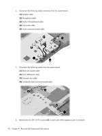
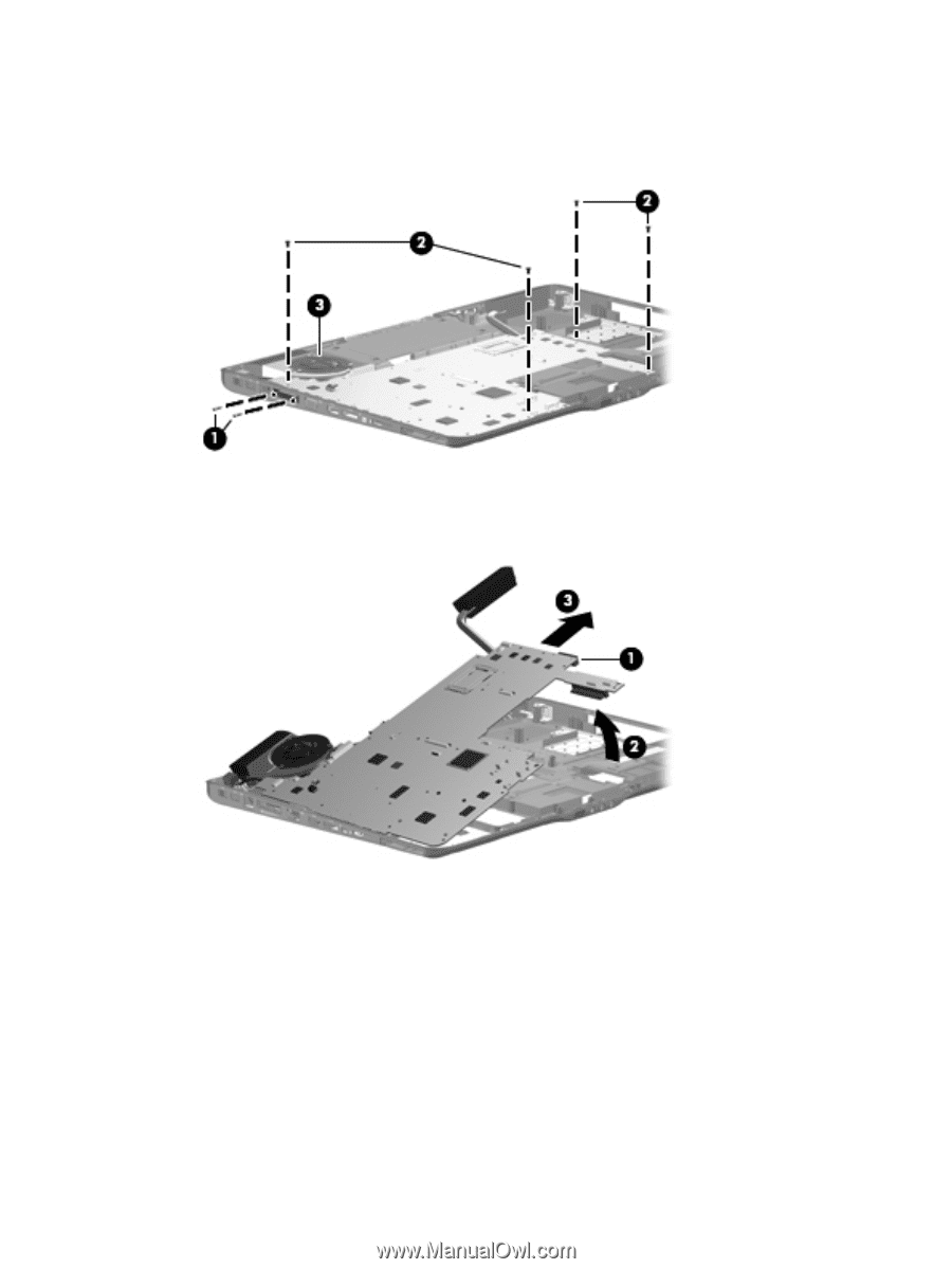
6. Remove the four Phillips PM2.5×4.0 screws (2) that secure the system board to the base enclosure. 7. Loosen the captive Phillips PM2.5×14.0 screw (3) that secures the video heat sink and system board to the base enclosure. 8. Use the optical drive connector (1) to lift the right side of the system board (2) until it rests at an angle. 9. Remove the system board (3) by pulling it away from the base enclosure at an angle. Reverse this procedure to install the system board. Component replacement procedures 79
-
 1
1 -
2
-
3
-
4
-
5
-
6
-
7
-
8
-
9
-
10
-
11
-
12
-
13
-
14
-
15
-
16
-
17
-
18
-
19
-
20
-
21
-
22
-
23
-
24
-
25
-
26
-
27
-
28
-
29
-
30
-
31
-
32
-
33
-
34
-
35
-
36
-
37
-
38
-
39
-
40
-
41
-
42
-
43
-
44
-
45
-
46
-
47
-
48
-
49
-
50
-
51
-
52
-
53
-
54
-
55
-
56
-
57
-
58
-
59
-
60
-
61
-
62
-
63
-
64
-
65
-
66
-
67
-
68
-
69
-
70
-
71
-
72
-
73
-
74
-
75
-
76
-
77
-
78
-
79
-
80
-
81
-
 82
82 -
 83
83 -
 84
84 -
 85
85 -
 86
86 -
 87
87 -
 88
88 -
 89
89 -
 90
90 -
 91
91 -
 92
92 -
93
-
94
-
95
-
96
-
97
-
98
-
99
-
100
-
101
-
102
-
103
-
104
-
105
-
106
-
107
-
108
-
109
-
110
-
111
-
112
-
113
-
114
-
115
-
116
-
117
-
118
-
119
-
120
-
121
-
122
-
123
-
124
-
125
-
126
-
127
-
128
-
129
-
130
-
131
-
132
-
133
-
134
-
135
-
136
-
137
-
138
-
139
-
140
-
141
-
142
-
143
-
144
-
145
-
146
-
147
-
148
-
149
-
150
-
151
-
152
-
153
-
154
-
155
-
156
-
157
-
158
-
159
-
160
-
161
-
162
-
163
 |
 |
6
.
Remove the four Phillips PM2.5×4.0 screws
(2)
that secure the system board to the base enclosure.
7
.
Loosen the captive Phillips PM2.5×14.0 screw
(3)
that secures the video heat sink and system board
to the base enclosure.
8
.
Use the optical drive connector
(1)
to lift the right side of the system board
(2)
until it rests at an
angle.
9
.
Remove the system board
(3)
by pulling it away from the base enclosure at an angle.
Reverse this procedure to install the system board.
Component replacement procedures
79