HP Pavilion HDX9575LA HP Pavilion HDX Entertainment Notebook PC - Maintenance - Page 56
Remove the WLAN module, The edge of the module opposite the slot rises away from the computer.
 |
View all HP Pavilion HDX9575LA manuals
Add to My Manuals
Save this manual to your list of manuals |
Page 56 highlights
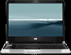
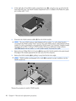
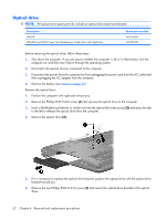
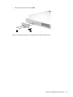
3. Lift the right side of the WLAN module compartment cover (2), swing the cover up and to the left, and remove the cover. The WLAN module compartment cover is included in the Plastics Kit, spare part number 448171-001. 4. Disconnect the WLAN antenna cables (1) from the WLAN module. NOTE: The main WLAN antenna cable (labeled with the number 1 or with a black band) is connected to the WLAN module "Main" terminal. The white WLAN antenna cable (labeled with the number 2 or with a white band) is connected to the WLAN module "Aux" terminal. Computer models equipped with an 802.11a/b/g/n WLAN module will have an additional wireless antenna cable (2) (labeled with the number 3 or with a yellow band). Disconnect this cable. 5. Remove the two Phillips PM2.5×5.0 screws (3) that secure the WLAN module to the system board. (The edge of the module opposite the slot rises away from the computer.) 6. Remove the WLAN module (4) by pulling it away from the slot at an angle. NOTE: WLAN modules are designed with a notch (5) to prevent incorrect installation into the WLAN module slot. Reverse this procedure to install a WLAN module. 48 Chapter 4 Removal and replacement procedures
-
 1
1 -
2
-
3
-
4
-
5
-
6
-
7
-
8
-
9
-
10
-
11
-
12
-
13
-
14
-
15
-
16
-
17
-
18
-
19
-
20
-
21
-
22
-
23
-
24
-
25
-
26
-
27
-
28
-
29
-
30
-
31
-
32
-
33
-
34
-
35
-
36
-
37
-
38
-
39
-
40
-
41
-
42
-
43
-
44
-
45
-
46
-
47
-
48
-
49
-
50
-
 51
51 -
 52
52 -
 53
53 -
 54
54 -
 55
55 -
 56
56 -
 57
57 -
 58
58 -
 59
59 -
 60
60 -
 61
61 -
62
-
63
-
64
-
65
-
66
-
67
-
68
-
69
-
70
-
71
-
72
-
73
-
74
-
75
-
76
-
77
-
78
-
79
-
80
-
81
-
82
-
83
-
84
-
85
-
86
-
87
-
88
-
89
-
90
-
91
-
92
-
93
-
94
-
95
-
96
-
97
-
98
-
99
-
100
-
101
-
102
-
103
-
104
-
105
-
106
-
107
-
108
-
109
-
110
-
111
-
112
-
113
-
114
-
115
-
116
-
117
-
118
-
119
-
120
-
121
-
122
-
123
-
124
-
125
-
126
-
127
-
128
-
129
-
130
-
131
-
132
-
133
-
134
-
135
-
136
-
137
-
138
-
139
-
140
-
141
-
142
-
143
-
144
-
145
-
146
-
147
-
148
-
149
-
150
-
151
-
152
-
153
-
154
-
155
-
156
-
157
-
158
-
159
-
160
-
161
-
162
-
163
 |
 |
