HP Pavilion HDX9575LA HP Pavilion HDX Entertainment Notebook PC - Maintenance - Page 82
Battery, on Hard drive, Optical drive, Keyboard, Hinge cover, Rear cover, Top cover, Subwoofer
 |
View all HP Pavilion HDX9575LA manuals
Add to My Manuals
Save this manual to your list of manuals |
Page 82 highlights
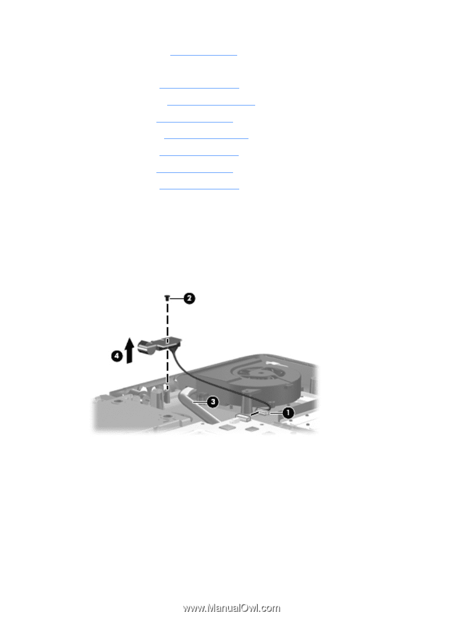
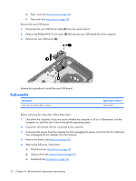
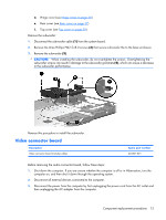
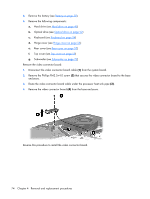
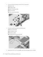
4. Remove the battery (see Battery on page 38). 5. Remove the following components: a. Hard drive (see Hard drive on page 45) b. Optical drive (see Optical drive on page 52) c. Keyboard (see Keyboard on page 54) d. Hinge cover (see Hinge cover on page 56) e. Rear cover (see Rear cover on page 57) f. Top cover (see Top cover on page 59) g. Subwoofer (see Subwoofer on page 72) Remove the video connector board: 1. Disconnect the video connector board cable (1) from the system board. 2. Remove the Phillips PM2.5×4.0 screw (2) that secures the video connector board to the base enclosure. 3. Route the video connector board cable under the processor heat sink pipe (3). 4. Remove the video connector board (4) from the base enclosure. Reverse this procedure to install the video connector board. 74 Chapter 4 Removal and replacement procedures
-
 1
1 -
2
-
3
-
4
-
5
-
6
-
7
-
8
-
9
-
10
-
11
-
12
-
13
-
14
-
15
-
16
-
17
-
18
-
19
-
20
-
21
-
22
-
23
-
24
-
25
-
26
-
27
-
28
-
29
-
30
-
31
-
32
-
33
-
34
-
35
-
36
-
37
-
38
-
39
-
40
-
41
-
42
-
43
-
44
-
45
-
46
-
47
-
48
-
49
-
50
-
51
-
52
-
53
-
54
-
55
-
56
-
57
-
58
-
59
-
60
-
61
-
62
-
63
-
64
-
65
-
66
-
67
-
68
-
69
-
70
-
71
-
72
-
73
-
74
-
75
-
76
-
 77
77 -
 78
78 -
 79
79 -
 80
80 -
 81
81 -
 82
82 -
 83
83 -
 84
84 -
 85
85 -
 86
86 -
 87
87 -
88
-
89
-
90
-
91
-
92
-
93
-
94
-
95
-
96
-
97
-
98
-
99
-
100
-
101
-
102
-
103
-
104
-
105
-
106
-
107
-
108
-
109
-
110
-
111
-
112
-
113
-
114
-
115
-
116
-
117
-
118
-
119
-
120
-
121
-
122
-
123
-
124
-
125
-
126
-
127
-
128
-
129
-
130
-
131
-
132
-
133
-
134
-
135
-
136
-
137
-
138
-
139
-
140
-
141
-
142
-
143
-
144
-
145
-
146
-
147
-
148
-
149
-
150
-
151
-
152
-
153
-
154
-
155
-
156
-
157
-
158
-
159
-
160
-
161
-
162
-
163
 |
 |