HP Pavilion HDX9575LA HP Pavilion HDX Entertainment Notebook PC - Maintenance - Page 59
Memory modules are designed with a notch, by pulling it away from the slot at an angle.
 |
View all HP Pavilion HDX9575LA manuals
Add to My Manuals
Save this manual to your list of manuals |
Page 59 highlights
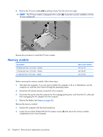
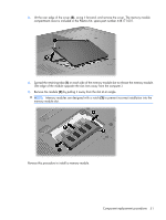
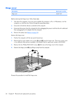
3. Lift the rear edge of the cover (2), swing it forward, and remove the cover. The memory module compartment cover is included in the Plastics Kit, spare part number 448171-001. 4. Spread the retaining tabs (1) on each side of the memory module slot to release the memory module. (The edge of the module opposite the slot rises away from the computer.) 5. Remove the module (2) by pulling it away from the slot at an angle. NOTE: Memory modules are designed with a notch (3) to prevent incorrect installation into the memory module slot. Reverse this procedure to install a memory module. Component replacement procedures 51
-
 1
1 -
2
-
3
-
4
-
5
-
6
-
7
-
8
-
9
-
10
-
11
-
12
-
13
-
14
-
15
-
16
-
17
-
18
-
19
-
20
-
21
-
22
-
23
-
24
-
25
-
26
-
27
-
28
-
29
-
30
-
31
-
32
-
33
-
34
-
35
-
36
-
37
-
38
-
39
-
40
-
41
-
42
-
43
-
44
-
45
-
46
-
47
-
48
-
49
-
50
-
51
-
52
-
53
-
 54
54 -
 55
55 -
 56
56 -
 57
57 -
 58
58 -
 59
59 -
 60
60 -
 61
61 -
 62
62 -
 63
63 -
 64
64 -
65
-
66
-
67
-
68
-
69
-
70
-
71
-
72
-
73
-
74
-
75
-
76
-
77
-
78
-
79
-
80
-
81
-
82
-
83
-
84
-
85
-
86
-
87
-
88
-
89
-
90
-
91
-
92
-
93
-
94
-
95
-
96
-
97
-
98
-
99
-
100
-
101
-
102
-
103
-
104
-
105
-
106
-
107
-
108
-
109
-
110
-
111
-
112
-
113
-
114
-
115
-
116
-
117
-
118
-
119
-
120
-
121
-
122
-
123
-
124
-
125
-
126
-
127
-
128
-
129
-
130
-
131
-
132
-
133
-
134
-
135
-
136
-
137
-
138
-
139
-
140
-
141
-
142
-
143
-
144
-
145
-
146
-
147
-
148
-
149
-
150
-
151
-
152
-
153
-
154
-
155
-
156
-
157
-
158
-
159
-
160
-
161
-
162
-
163
 |
 |

3
.
Lift the rear edge of the cover
(2)
, swing it forward, and remove the cover. The memory module
compartment cover is included in the Plastics Kit, spare part number 448171-001.
4
.
Spread the retaining tabs
(1)
on each side of the memory module slot to release the memory module.
(The edge of the module opposite the slot rises away from the computer.)
5
.
Remove the module
(2)
by pulling it away from the slot at an angle.
NOTE:
Memory modules are designed with a notch
(3)
to prevent incorrect installation into the
memory module slot.
Reverse this procedure to install a memory module.
Component replacement procedures
51