HP ProBook 4311s HP ProBook 4310s Notebook PC and HP ProBook 4311s Notebook PC - Page 81
Top cover, Display assembly see
 |
View all HP ProBook 4311s manuals
Add to My Manuals
Save this manual to your list of manuals |
Page 81 highlights
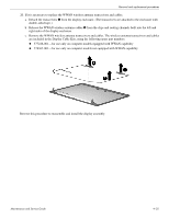
Removal and replacement procedures Top cover ✎ The top cover spare part kit includes a palm rest, TouchPad and cable, and TouchPad button board and cable. Description Spare part number For use only on computer models equipped with fingerprint reader in black trim (includes fingerprint 577216-001 reader board and cable) For use only on computer models equipped with fingerprint reader in red trim (includes fingerprint 577218-001 reader board and cable) For use only on computer models not equipped with fingerprint reader in black trim 577217-001 For use only on computer models not equipped with fingerprint reader in red trim 577219-001 Before removing the top cover, follow these steps: 1. Shut down the computer. If you are unsure whether the computer is off or in Hibernation, turn the computer on, and then shut it down through the operating system. 2. Disconnect all external devices connected to the computer. 3. Disconnect the power from the computer by first unplugging the power cord from the AC outlet, and then unplugging the AC adapter from the computer. 4. Remove the battery (see "Battery" on page 4-7). 5. Remove the following components: a. Hard drive (see "Hard drive" on page 4-9) b. Memory/wireless module compartment cover (see "WLAN module" on page 4-12) c. Optical drive (see "Optical drive" on page 4-18) d. Keyboard and switch cover (see "Keyboard and switch cover" on page 4-20) e. Palm rest (see "Palm rest" on page 4-25) f. Display assembly (see "Display assembly" on page 4-27) Remove the top cover: 1. Turn the computer upside down, with the front toward you. 2. Remove the four slotted Torx T8M2.5×7.0 screws 1 and the three Phillips PM2.0×3.0 screws 2 that secure the top cover to the base enclosure. 4-36 Maintenance and Service Guide
-
 1
1 -
2
-
3
-
4
-
5
-
6
-
7
-
8
-
9
-
10
-
11
-
12
-
13
-
14
-
15
-
16
-
17
-
18
-
19
-
20
-
21
-
22
-
23
-
24
-
25
-
26
-
27
-
28
-
29
-
30
-
31
-
32
-
33
-
34
-
35
-
36
-
37
-
38
-
39
-
40
-
41
-
42
-
43
-
44
-
45
-
46
-
47
-
48
-
49
-
50
-
51
-
52
-
53
-
54
-
55
-
56
-
57
-
58
-
59
-
60
-
61
-
62
-
63
-
64
-
65
-
66
-
67
-
68
-
69
-
70
-
71
-
72
-
73
-
74
-
75
-
 76
76 -
 77
77 -
 78
78 -
 79
79 -
 80
80 -
 81
81 -
 82
82 -
 83
83 -
 84
84 -
 85
85 -
 86
86 -
87
-
88
-
89
-
90
-
91
-
92
-
93
-
94
-
95
-
96
-
97
-
98
-
99
-
100
-
101
-
102
-
103
-
104
-
105
-
106
-
107
-
108
-
109
-
110
-
111
-
112
-
113
-
114
-
115
-
116
-
117
-
118
-
119
-
120
-
121
-
122
-
123
-
124
-
125
-
126
-
127
-
128
-
129
-
130
-
131
-
132
-
133
-
134
-
135
-
136
-
137
-
138
-
139
-
140
-
141
-
142
-
143
-
144
-
145
-
146
-
147
-
148
-
149
-
150
-
151
-
152
-
153
-
154
-
155
-
156
-
157
-
158
-
159
 |
 |
