HP ProBook 4311s HP ProBook 4310s Notebook PC and HP ProBook 4311s Notebook PC - Page 91
Power button board, Release the two ZIF connectors
 |
View all HP ProBook 4311s manuals
Add to My Manuals
Save this manual to your list of manuals |
Page 91 highlights
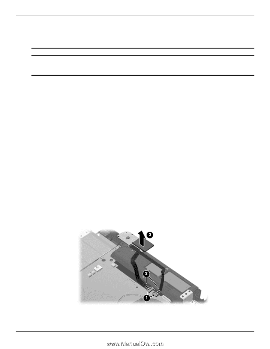
Removal and replacement procedures Power button board ✎ The power button board spare part kit includes two cables. Description Power button board for use only on computer models equipped with WWAN capability (includes SIM slot) Power button board for use only on computer models not equipped with WWAN capability Spare part number 577662-001 577661-001 Before removing the power button board, follow these steps: 1. Shut down the computer. If you are unsure whether the computer is off or in Hibernation, turn the computer on, and then shut it down through the operating system. 2. Disconnect all external devices connected to the computer. 3. Disconnect the power from the computer by first unplugging the power cord from the AC outlet, and then unplugging the AC adapter from the computer. 4. Remove the battery (see "Battery" on page 4-7). 5. Remove the following components: a. Hard drive (see "Hard drive" on page 4-9) b. Memory/wireless module compartment cover (see "WLAN module" on page 4-12) c. Optical drive (see "Optical drive" on page 4-18) d. Keyboard and switch cover (see "Keyboard and switch cover" on page 4-20) e. Palm rest (see "Palm rest" on page 4-25) f. Display assembly (see "Display assembly" on page 4-27) g. Top cover (see "Top cover" on page 4-36) Remove the power button board: 1. Release the two ZIF connectors 1 to which the two power button board cables are attached, and then disconnect the cables 2 from the system board. 2. Detach the power button board 3 from the base enclosure. (The power button board is attached to the base enclosure with double-sided tape.) 3. Remove the power button board and cables. Reverse this procedure to install the power button board. 4-46 Maintenance and Service Guide
-
 1
1 -
2
-
3
-
4
-
5
-
6
-
7
-
8
-
9
-
10
-
11
-
12
-
13
-
14
-
15
-
16
-
17
-
18
-
19
-
20
-
21
-
22
-
23
-
24
-
25
-
26
-
27
-
28
-
29
-
30
-
31
-
32
-
33
-
34
-
35
-
36
-
37
-
38
-
39
-
40
-
41
-
42
-
43
-
44
-
45
-
46
-
47
-
48
-
49
-
50
-
51
-
52
-
53
-
54
-
55
-
56
-
57
-
58
-
59
-
60
-
61
-
62
-
63
-
64
-
65
-
66
-
67
-
68
-
69
-
70
-
71
-
72
-
73
-
74
-
75
-
76
-
77
-
78
-
79
-
80
-
81
-
82
-
83
-
84
-
85
-
 86
86 -
 87
87 -
 88
88 -
 89
89 -
 90
90 -
 91
91 -
 92
92 -
 93
93 -
 94
94 -
 95
95 -
 96
96 -
97
-
98
-
99
-
100
-
101
-
102
-
103
-
104
-
105
-
106
-
107
-
108
-
109
-
110
-
111
-
112
-
113
-
114
-
115
-
116
-
117
-
118
-
119
-
120
-
121
-
122
-
123
-
124
-
125
-
126
-
127
-
128
-
129
-
130
-
131
-
132
-
133
-
134
-
135
-
136
-
137
-
138
-
139
-
140
-
141
-
142
-
143
-
144
-
145
-
146
-
147
-
148
-
149
-
150
-
151
-
152
-
153
-
154
-
155
-
156
-
157
-
158
-
159
 |
 |