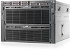
HP ProLiant DL980 DL980 G7 Maintenance & Service Guide
HP ProLiant DL980 - G7 Server Manual
 |
View all HP ProLiant DL980 manuals
Add to My Manuals
Save this manual to your list of manuals |
HP ProLiant DL980 manual content summary:
- HP ProLiant DL980 | DL980 G7 Maintenance & Service Guide - Page 1
HP ProLiant DL980 G7 Server Maintenance and Service Guide Part Number AM426-9001A September 2010 (First Edition) - HP ProLiant DL980 | DL980 G7 Maintenance & Service Guide - Page 2
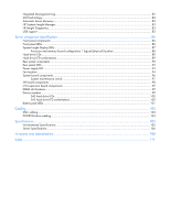
XNC module...73 System board...74 Power backplane...76 HP Trusted Platform Module ...78 Diagnostic tools ...79 Troubleshooting resources ...79 SmartStart software ...79 SmartStart Scripting Toolkit ...80 HP Insight Remote Support software ...80 Option ROM Configuration for Arrays ...80 HP ROM-Based - HP ProLiant DL980 | DL980 G7 Maintenance & Service Guide - Page 3
...82 Automatic Server Recovery ...83 HP Systems Insight Manager ...83 HP Insight Diagnostics...83 USB support ...83 Server component identification...85 Front panel components ...85 Front panel LEDs ...86 System Insight Display LEDs ...87 Processor and memory board configuration / logical (physical - HP ProLiant DL980 | DL980 G7 Maintenance & Service Guide - Page 4
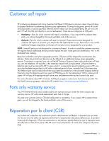
.Intended audienceThis guide is for an experienced service technician. HP assumes you are qualified in the servicing of computer equipment and trained in recognizing hazards in products with hazardous energy levels and are familiar with weight and stability precautions for rack installations. - HP ProLiant DL980 | DL980 G7 Maintenance & Service Guide - Page 5
service designated for your product. NOTE: Some HP parts are not designed for customer self repair. In order to satisfy the customer warranty, HP requires that an authorized service provider can call the HP Technical Support Center and a technician will help you over the telephone. HP specifies in - HP ProLiant DL980 | DL980 G7 Maintenance & Service Guide - Page 6
pièce défectueuse, HP se réserve le droit de vous facturer les coûts de remplacement. Dans le cas d'une pièce CSR, HP supporte l'ensemble des frais le site Web HP (http://www.hp.com/go/selfrepair). Service de garantie "pièces seules" Votre garantie limitée HP peut inclure un service de garantie "pi - HP ProLiant DL980 | DL980 G7 Maintenance & Service Guide - Page 7
Self Repair ausgelegt. Wenn Sie jedoch den Austausch dieser Teile von HP vornehmen lassen möchten, können bei diesem Service je nach den für Ihr Produkt vorgesehenen Garantiebedingungen zusätzliche Kosten . Wenn Sie Hilfe benötigen, können Sie das HP technische Support Center Customer self repair 7 - HP ProLiant DL980 | DL980 G7 Maintenance & Service Guide - Page 8
CSR-Verfahren zwingend vorgegeben. Wenn Sie den Austausch dieser Teile von HP vornehmen lassen, werden Ihnen die Anfahrt- und Arbeitskosten für diesen Service berechnet. Reparaciones del propio cliente Los productos de HP incluyen muchos componentes que el propio usuario puede reemplazar (Customer - HP ProLiant DL980 | DL980 G7 Maintenance & Service Guide - Page 9
worden CSR-onderdelen (Customer Self Repair) genoemd. Als HP (of een HP Service Partner) bij de diagnose vaststelt dat de reparatie kan worden gebracht, afhankelijk van het type garantieservice voor het product. OPMERKING: Sommige HP onderdelen zijn niet ontwikkeld voor reparatie door de klant - HP ProLiant DL980 | DL980 G7 Maintenance & Service Guide - Page 10
voor meer informatie over het Customer Self Repair programma van HP. Informatie over Service Partners vindt u op de HP website (http://www.hp.com/go/selfrepair). Garantieservice "Parts Only" Het is mogelijk dat de HP garantie alleen de garantieservice "Parts Only" omvat. Volgens de bepalingen - HP ProLiant DL980 | DL980 G7 Maintenance & Service Guide - Page 11
peças. Segundo os termos do serviço de garantia apenas para peças, a HP fornece as peças de reposição sem cobrar nenhuma taxa. No caso desse serviço, a substituição de peças CSR é obrigatória. Se desejar que a HP substitua essas peças, serão cobradas as despesas de transporte e mão-de-obra do - HP ProLiant DL980 | DL980 G7 Maintenance & Service Guide - Page 12
Customer self repair 12 - HP ProLiant DL980 | DL980 G7 Maintenance & Service Guide - Page 13
Customer self repair 13 - HP ProLiant DL980 | DL980 G7 Maintenance & Service Guide - Page 14
Customer self repair 14 - HP ProLiant DL980 | DL980 G7 Maintenance & Service Guide - Page 15
Customer self repair 15 - HP ProLiant DL980 | DL980 G7 Maintenance & Service Guide - Page 16
Mechanical Components Item 1 2 3 4 5 6 Description Spare part number Access panel Processor memory drawer top Bezel, processor memory drawer top Blank, hard drive Bezel assembly, power, SID Bezel Processor memory drawer bottom Blank, lower processor memory AM426-69016 AM426-69002 AM426-69019 - HP ProLiant DL980 | DL980 G7 Maintenance & Service Guide - Page 17
Item Description Spare part number Customer self repair (on page 5) drawer* Bezel, Processor memory drawer bottom AM426-69020 Mandatory1 7 Tool, T-15 Torx 199630-001 Mandatory1 8 Blank, power supply 496058-001 Mandatory1 Plastics Kit* AM426-69014 Mandatory1 3-8 U Slide rail kit* - HP ProLiant DL980 | DL980 G7 Maintenance & Service Guide - Page 18
garantieservice voor het product. 3No: Nee-Sommige HP onderdelen zijn niet Service Partner worden vervangen. Deze onderdelen worden in de geïllustreerde onderdelencatalogus aangemerkt met "Nee". 1Mandatory: Obrigatória-Peças cujo reparo feito pelo cliente é obrigatório. Se desejar que a HP - HP ProLiant DL980 | DL980 G7 Maintenance & Service Guide - Page 19
Illustrated parts catalog 19 - HP ProLiant DL980 | DL980 G7 Maintenance & Service Guide - Page 20
1 2 Mandatory13 4 5 6 7 Description Spare part number PCI-X/PCI Express i/O expansion board PCI Express I/O expansion board System board SPI Board Memory module 591204-001 591205-001 AM426-69015 AM426-69017 591198-001 Heatsink-assembly 591207-001 Memory - a) DIMM, 2-GB, PC310600R, 128x8 MB - HP ProLiant DL980 | DL980 G7 Maintenance & Service Guide - Page 21
number Processors 4c 1.86GHz 18M 95W 6c 2.0GHz 18M 105W 8c 2.0GHz 18M 130W 8c 2.27GHz 24M 130W Power backplane 597821-001 597899-001 594896-001 594893-001 AM426-69001 PCA, memory riser board Memory cartridge 512842-001 591198-001 Fan 591208-001 SAS backplane 591203-001 Systems Power supply - HP ProLiant DL980 | DL980 G7 Maintenance & Service Guide - Page 22
battery* * Cable assembly, 501025-001 Optional2 SATA power/data * Cable assembly, mini- 498426-001 number 453834-001). 1Mandatory-Parts for which customer self repair is mandatory. If you request HP to replace these parts, you will be charged for the travel and labor costs of this service - HP ProLiant DL980 | DL980 G7 Maintenance & Service Guide - Page 23
Wenn Sie jedoch den Austausch dieser Teile von HP vornehmen lassen möchten, können bei diesem Service je nach den für Ihr Produkt vorgesehenen gebracht, afhankelijk van het type garantieservice voor het product. 3No: Nee-Sommige HP onderdelen zijn niet ontwikkeld voor reparatie door de klant - HP ProLiant DL980 | DL980 G7 Maintenance & Service Guide - Page 24
-Peças cujo reparo feito pelo cliente é opcional. Essas peças também são projetadas para o reparo feito pelo cliente. No entanto, se desejar que a HP as substitua, pode haver ou não a cobrança de taxa adicional, dependendo do tipo de serviço de garantia destinado ao produto. 3No: Nenhuma-Algumas pe - HP ProLiant DL980 | DL980 G7 Maintenance & Service Guide - Page 25
warnings and cautions Before installing a server, be sure that you understand the following warnings and cautions. WARNING: To reduce the risk of electric shock or damage to the equipment: • Do not disable the power cord grounding plug. The grounding plug is an important safety feature. • Plug - HP ProLiant DL980 | DL980 G7 Maintenance & Service Guide - Page 26
to the equipment, remove the power cord to remove power from the server. The front panel Power On/Standby button does not completely shut off system power. Portions of the power supply and some internal circuitry remain active until AC power is removed. IMPORTANT: If installing a hot-plug device, it - HP ProLiant DL980 | DL980 G7 Maintenance & Service Guide - Page 27
from the rack. WARNING: To reduce the risk of personal injury, be careful when pressing the server railrelease latches and sliding the server into the rack. The sliding rails could pinch your fingers. To extend the server from the rack: 1. Pull down the quick-release levers on each side of the - HP ProLiant DL980 | DL980 G7 Maintenance & Service Guide - Page 28
hot surfaces, allow the drives and the internal system components to cool before touching them. CAUTION: For proper cooling do not operate the server without the access panel, baffles, expansion slot covers, or blanks installed. If the server supports hot-plug components, minimize the amount of time - HP ProLiant DL980 | DL980 G7 Maintenance & Service Guide - Page 29
To remove the component: 1. Power down the server if performing a non-hot-plug installation or maintenance procedure ("Power down the server" on page 26). 2. Extend the server from the rack. 3. Use the T-15 Torx screwdriver attached to the rear of the server to loosen the security screw on the hood - HP ProLiant DL980 | DL980 G7 Maintenance & Service Guide - Page 30
do not operate the server without the access panel, baffles, expansion slot covers, or blanks installed. If the server supports hot-plug components, ("SAS hard drive LED combinations" on page 100). 2. Back up all server data on the hard drive. 3. Remove the hard drive. To replace the component - HP ProLiant DL980 | DL980 G7 Maintenance & Service Guide - Page 31
power supply The server supports up to four hot-plug power supplies. Install all power supplies to provide full redundancy. HP recommends installing redundant hot-plug power supplies in pairs. To confirm the redundancy of your configuration, see the HP power advisor at the HP website (http://www.hp - HP ProLiant DL980 | DL980 G7 Maintenance & Service Guide - Page 32
to the plug, electrical outlet, and the point where the cord extends from the server. To remove the component: 1. Disconnect the power cord from the failed power supply. 2. Remove the failed power supply. To replace the component, reverse the removal procedure. Upper fans To remove the component - HP ProLiant DL980 | DL980 G7 Maintenance & Service Guide - Page 33
the removal procedure. Lower fan module To remove the component: 1. Extend the server from the rack. 2. Remove the fan module. To replace the component, reverse the removal procedure. Memory cartridge To remove the component: 1. Power down the server (on page 26). Illustrated parts catalog 33 - HP ProLiant DL980 | DL980 G7 Maintenance & Service Guide - Page 34
2. Remove the processor memory drawer (on page 29). 3. Remove the processor memory drawer cover. 4. Remove the failed memory cartridge. 5. Open the memory cartridge cover. 6. Remove the DIMMs from the failed memory cartridge: a. Open the DIMM slot latches. Illustrated parts catalog 34 - HP ProLiant DL980 | DL980 G7 Maintenance & Service Guide - Page 35
b. Remove the DIMM. To replace the component: 1. Install the DIMMs in the replacement memory cartridge: a. Open the DIMM slot latches. b. Install the DIMM. 2. Close the memory cartridge cover. Illustrated parts catalog 35 - HP ProLiant DL980 | DL980 G7 Maintenance & Service Guide - Page 36
Install the memory cartridge. 4. Install the processor memory drawer cover. 5. Install the processor memory drawer. 6. Power up the server. Installing memory 1. Power down the server (on page 26). 2. Remove the processor memory drawer (on page 29). CAUTION: To prevent damage to the processor memory - HP ProLiant DL980 | DL980 G7 Maintenance & Service Guide - Page 37
4. Remove the memory cartridge. 5. Open the memory cartridge cover. 6. Open the DIMM slot latches. Illustrated parts catalog 37 - HP ProLiant DL980 | DL980 G7 Maintenance & Service Guide - Page 38
options (on page 41)." 8. Close the memory cartridge cover. 9. Install the memory cartridge. 10. Install the processor memory drawer cover. 11. Install the processor memory drawer. 12. Power up the server. DIMMs To remove the component: 1. Power down the server (on page 26). 2. Remove the processor - HP ProLiant DL980 | DL980 G7 Maintenance & Service Guide - Page 39
3. Remove the processor memory drawer cover. 4. Remove the memory cartridge. 5. Open the memory cartridge cover. 6. Remove the failed DIMM from the memory cartridge: a. Open the DIMM slot latches. Illustrated parts catalog 39 - HP ProLiant DL980 | DL980 G7 Maintenance & Service Guide - Page 40
b. Remove the DIMM. To replace the component: 1. Install the replacement DIMM in the memory cartridge: a. Open the DIMM slot latches. b. Install the DIMM. 2. Close the memory cartridge cover. Illustrated parts catalog 40 - HP ProLiant DL980 | DL980 G7 Maintenance & Service Guide - Page 41
Install the processor memory drawer. 6. Power up the server. Memory options This server contains eight memory cartridge connectors in each processor memory drawer. Each memory cartridge can contain eight DIMMs, for a total of 128 DIMMs, for a maximum memory configuration of 2 TB. The server supports - HP ProLiant DL980 | DL980 G7 Maintenance & Service Guide - Page 42
at a time. The server memory control subsystem selects the proper rank within the DIMM when writing to or reading from the DIMM. Dual- and quad-rank DIMMs provide the greatest capacity with the existing memory technology. For example, if current DRAM technology supports 2-GB single-rank DIMMs - HP ProLiant DL980 | DL980 G7 Maintenance & Service Guide - Page 43
DIMM pairs offer larger memory protection to provide increased memory fault resiliency. • DIMMs must be installed in quads with identical characteristics. When possible, for configuration simplicity, HP recommends using DIMMs with identical part numbers throughout the system. • DIMM quads must be - HP ProLiant DL980 | DL980 G7 Maintenance & Service Guide - Page 44
to the system if the associated processor is installed. Do not install memory cartridges in cartridge slots without the corresponding processor installed. • Two DIMM populated memory cartridges are required per processor. • To maximize performance in multi-processor configurations, distribute the - HP ProLiant DL980 | DL980 G7 Maintenance & Service Guide - Page 45
largest contributor to maximum memory bandwidth performance is to use both memory controllers inside the processor. To achieve maximum memory bandwidth performance, populate both memory cartridges for each installed processor. This configuration is required for this server. Illustrated parts catalog - HP ProLiant DL980 | DL980 G7 Maintenance & Service Guide - Page 46
. For more information, see "Mirrored Memory population guidelines (on page 48)." AMP modes are configured in RBSU. If the requested AMP mode is not supported by the installed DIMM configuration, the server boots in Advanced ECC mode. For more information, see "HP ROM-Based Setup Utility (on page - HP ProLiant DL980 | DL980 G7 Maintenance & Service Guide - Page 47
the latest memory configuration information, see the QuickSpecs on the HP website (http://www.hp.com/go/ProLiant). Advanced ECC memory population guidelines Advanced ECC memory is the default memory protection mode for the server. Up to 2-TB of active memory using 16-GB DIMMs is supported in this - HP ProLiant DL980 | DL980 G7 Maintenance & Service Guide - Page 48
• Although this configuration requirement is the same for Hemisphere mode and Mirrored Memory mode, only one of the two modes can be enabled at a given time. • Both of the CPU sockets on the same QPI island must be loaded with identical memory. Installing memory 1. Power down the server (on page 26 - HP ProLiant DL980 | DL980 G7 Maintenance & Service Guide - Page 49
4. Open the memory cartridge cover. 5. Open the DIMM slot latches. 6. Install the DIMM. See "Memory options (on page 41)." 7. Close the memory cartridge cover. Illustrated parts catalog 49 - HP ProLiant DL980 | DL980 G7 Maintenance & Service Guide - Page 50
8. Install the memory cartridge. 9. Install the processor memory drawer cover. 10. Install the processor memory drawer. 11. Power up the server. Heatsink To remove the component: 1. Power down the server (on page 26). 2. Remove the processor memory drawer (on page 29). 3. Remove the processor memory - HP ProLiant DL980 | DL980 G7 Maintenance & Service Guide - Page 51
4. Open the processor retaining bracket. 5. Remove the heatsink. To replace the component: 1. Clean the old thermal grease from the top of the processor with the alcohol swab. Allow the alcohol to evaporate before continuing. Illustrated parts catalog 51 - HP ProLiant DL980 | DL980 G7 Maintenance & Service Guide - Page 52
2. Remove the heatsink protective cover. 3. Install the heatsink. 4. Close and lock the processor retaining bracket. 5. Install the processor memory drawer cover. 6. Install the processor memory drawer. 7. Power up the server. To replace the component, reverse the removal procedure. Illustrated - HP ProLiant DL980 | DL980 G7 Maintenance & Service Guide - Page 53
system board, do not install the processor without using the processor installation tool. CAUTION: To prevent possible server malfunction and damage to the equipment, multiprocessor configurations must contain processors with the same part number. To remove the component: 1. Power down the server - HP ProLiant DL980 | DL980 G7 Maintenance & Service Guide - Page 54
4. Open the processor retaining bracket. 5. Remove the heatsink. Illustrated parts catalog 54 - HP ProLiant DL980 | DL980 G7 Maintenance & Service Guide - Page 55
6. Open the processor retaining latch and the processor socket retaining bracket. 7. Using your fingers, remove the failed processor. To replace the component: IMPORTANT: Be sure the processor remains inside the processor installation tool. Illustrated parts catalog 55 - HP ProLiant DL980 | DL980 G7 Maintenance & Service Guide - Page 56
the socket and install the spare processor. CAUTION: The processor is designed to fit one way into the socket. Use the alignment guides on the processor and socket to properly align the processor with the socket. Refer to the server hood label for specific instructions. Illustrated parts catalog - HP ProLiant DL980 | DL980 G7 Maintenance & Service Guide - Page 57
tool clicks and separates from the processor, and then remove the processor installation tool. 4. Close the processor retaining latch and the processor socket retaining bracket. 5. Clean the old thermal grease from the heatsink with the alcohol swab. Allow - HP ProLiant DL980 | DL980 G7 Maintenance & Service Guide - Page 58
one of the following patterns to ensure even distribution. 7. Install the heatsink. 8. Close and lock the processor retaining bracket. 9. Install the processor memory drawer cover. 10. Install the processor memory drawer. 11. Power up the server. Expansion slot cover Illustrated parts catalog 58 - HP ProLiant DL980 | DL980 G7 Maintenance & Service Guide - Page 59
unless all expansion slots have either an expansion slot cover or an expansion board installed. 1. Power down the server (on page 26). 2. Extend or remove the server from the rack. 3. Remove the access panel (on page 28). 4. Check for the shipping screw, and remove if present. 5. Open the latch - HP ProLiant DL980 | DL980 G7 Maintenance & Service Guide - Page 60
1. Press the release button, and open the lever. 2. Slide the I/O expander out of the server. Place a hand under the component to support it as you remove it from the server. 3. Press the side buttons to remove the component cover. Illustrated parts catalog 60 - HP ProLiant DL980 | DL980 G7 Maintenance & Service Guide - Page 61
improper cooling and thermal damage, do not operate the server unless all expansion slots have either an expansion slot cover or an expansion board installed. To remove the component: 1. Power down the server (on page 26). 2. Extend the server from the rack. 3. Remove the access panel (on page - HP ProLiant DL980 | DL980 G7 Maintenance & Service Guide - Page 62
to the expansion board. 6. Remove the retaining screw, if installed. 7. Remove the expansion board. To replace the component, reverse the removal procedure. Battery-backed write cache procedures Two types of procedures are provided for the BBWC option: • Removal and replacement of failed components - HP ProLiant DL980 | DL980 G7 Maintenance & Service Guide - Page 63
2. Extend the server from the rack. 3. Remove the access panel (on page 28). 4. If the existing cache is connected to a battery, observe the BBWC Status LED ("Battery pack LEDs" on page 101). o If the LED is flashing every 2 seconds, data is still trapped in the cache. Restore system power, and then - HP ProLiant DL980 | DL980 G7 Maintenance & Service Guide - Page 64
2. Extend the server from the rack. 3. Remove the access panel (on page 28). 4. If the existing cache is connected to a battery, observe the BBWC Status LED ("Battery pack LEDs" on page 101). o If the LED is flashing every 2 seconds, data is still trapped in the cache. Restore system power, and then - HP ProLiant DL980 | DL980 G7 Maintenance & Service Guide - Page 65
install any internal drives or BBWC in this server. (This is the preferred option.) o Find a server that has enough empty drive bays to accommodate all the drives from the failed server and that meets all the other requirements for drive and array migration. 2. Power down the failed server ("Power - HP ProLiant DL980 | DL980 G7 Maintenance & Service Guide - Page 66
through RBSU ("Re-entering the server serial number and product ID" on page 76). 5. Raise the levers, and lift the SPI board from the server. 6. Remove all components from the failed SPI board. To replace the component, reverse the removal procedure. Systems Insight Display assembly CAUTION: When - HP ProLiant DL980 | DL980 G7 Maintenance & Service Guide - Page 67
a replacement bezel on hand for immediate replacement before removing the bezel. 1. Power down the server (on page 26). 2. Extend the server from the rack. 3. Remove the access panel (on page 28). 4. Remove the SID bezel ("Systems Insight Display assembly" on page 66). Illustrated parts catalog 67 - HP ProLiant DL980 | DL980 G7 Maintenance & Service Guide - Page 68
5. Remove the seven screws from the right side of the chassis and eight screws from the left side of the chassis. 6. From the left and right insertion tabs, slide the upper part of the bezel forward. Illustrated parts catalog 68 - HP ProLiant DL980 | DL980 G7 Maintenance & Service Guide - Page 69
the processor memory drawers, the three catches on the lower part of the bezel, and remove the bezel. To replace the component, reverse the removal procedure., inserting the left side tab as the bezel is placed into position. Solid state drive To remove the component: 1. Power down the server (on - HP ProLiant DL980 | DL980 G7 Maintenance & Service Guide - Page 70
, short external contacts, or dispose of in fire or water. • Replace only with the spare designated for this product. To remove the component: 1. Power down the server (on page 26). 2. Extend the server from the rack. 3. Remove the access panel (on page 28). 4. Remove the SPI board (on page 66 - HP ProLiant DL980 | DL980 G7 Maintenance & Service Guide - Page 71
configuration, the second processor must be installed in socket 3. 1. Power down the server (on page 26). 2. Extend the server from the rack. 3. Remove the access panel (on page 28). 4. Release the latches on the release lever. 5. Lower the handle, and then extend the processor memory drawer - HP ProLiant DL980 | DL980 G7 Maintenance & Service Guide - Page 72
I/O expansion board o PCIe Express I/O expansion board To replace the component, reverse the removal procedure. SAS backplane To remove the component: 1. Power down the server (on page 26). 2. Extend the server from the rack. 3. Remove the access panel (on page 28). Illustrated parts catalog 72 - HP ProLiant DL980 | DL980 G7 Maintenance & Service Guide - Page 73
). 5. Disconnect all cables from the SAS backplane. 6. Release the locking latch. 7. Remove the SAS backplane. To replace the component, reverse the removal procedure. XNC module 1. Power down the server (on page 26). 2. Release the latches on the release lever. Illustrated parts catalog 73 - HP ProLiant DL980 | DL980 G7 Maintenance & Service Guide - Page 74
the system board requires replacement, contact HP Technical Support before proceeding. 1. Power down the server (on page 26). 2. Remove the server from the rack. 3. Remove the access panel (on page 28). 4. Remove the processor memory drawer (on page 29). 5. Disconnect all cables from all installed - HP ProLiant DL980 | DL980 G7 Maintenance & Service Guide - Page 75
all components removed from the failed system board. 3. Install the access panel. 4. Slide the server back into the rack. 5. Power up the server. After you replace the system board, you must re-enter the server serial number and the product ID. 1. During the server startup sequence, press the F9 key - HP ProLiant DL980 | DL980 G7 Maintenance & Service Guide - Page 76
drawers. ("Remove the processor memory drawer" on page 29) 8. Remove the system board ("Re-entering the server serial number and product ID" on page 76, "System board" on page 74). 9. Disconnect the upper cables from the power supply backplane. a. Disconnect the upper fan power cable. b. Remove the - HP ProLiant DL980 | DL980 G7 Maintenance & Service Guide - Page 77
cable from the cable management slot. 10. Disconnect the lower cables from the power supply backplane. a. Disconnect the lower fan power cable from the power backplane. b. Lift the release latch up. c. Disconnect the lower power cable from the power supply backplane. Illustrated parts catalog 77 - HP ProLiant DL980 | DL980 G7 Maintenance & Service Guide - Page 78
If you suspect a TPM board failure, leave the TPM installed and remove the system board ("Re-entering the server serial number and product ID" on page 76, "System board" on page 74). Contact an HP authorized service provider for a replacement system board and TPM board. Illustrated parts catalog 78 - HP ProLiant DL980 | DL980 G7 Maintenance & Service Guide - Page 79
on ProLiant servers and workstation blades. This guide includes problem-specific flowcharts to help you navigate complex troubleshooting processes. To view the guide, select a language: • English (http://www.hp.com/support/ProLiant_TSG_en) • Français (http://www.hp.com/support/ProLiant_TSG_fr - HP ProLiant DL980 | DL980 G7 Maintenance & Service Guide - Page 80
the HP website (http://www.hp.com/servers/sstoolkit). HP Insight Remote Support software HP strongly recommends that you install HP Insight Remote Support software to complete the installation or upgrade of your product and to enable enhanced delivery of your HP Warranty, HP Care Pack Service or HP - HP ProLiant DL980 | DL980 G7 Maintenance & Service Guide - Page 81
• Configuring memory options • Language selection For more information on RBSU, see the HP ROM-Based Setup Utility User Guide on the Documentation CD or the HP website (http://www.hp.com/support/smartstart/documentation). ROMPaq utility The ROMPaq utility enables you to upgrade the system firmware - HP ProLiant DL980 | DL980 G7 Maintenance & Service Guide - Page 82
supported by the server. For operating systems supported by the server, see the HP website (http://www.hp.com/support). • Integrates with other software maintenance, deployment, and operating system tools • Automatically checks for hardware, firmware, and operating system dependencies, and installs - HP ProLiant DL980 | DL980 G7 Maintenance & Service Guide - Page 83
and online versions, that provides diagnostics and troubleshooting capabilities to assist IT administrators who verify server installations, troubleshoot problems, and perform repair validation. HP Insight Diagnostics Offline Edition performs various in-depth system and component testing while the - HP ProLiant DL980 | DL980 G7 Maintenance & Service Guide - Page 84
• RBSU • Diagnostics • DOS • Operating environments which do not provide native USB support Diagnostic tools 84 - HP ProLiant DL980 | DL980 G7 Maintenance & Service Guide - Page 85
Server component identification Front panel components Item 1 2 3 4 5 6 7 8 9 10 11 12 13 14 15 16 17 Description Hard drive bay 1 bay 8 Optical drive bay UID button and LED Health LED NIC 1 LED NIC 2 LED NIC 3 LED NIC 4 LED Power on/Standby button and LED SID Server component identification 85 - HP ProLiant DL980 | DL980 G7 Maintenance & Service Guide - Page 86
Processor memory tray (upper) Processor memory tray (lower) Front panel LEDs Item Description 1 UID button and LED 2 Health LED 3 NIC 1 LED 4 NIC 2 LED 5 NIC 3 LED 6 NIC 4 LED Status Blue-Activated Blue (flashing)-Server being managed remotely Off-Deactivated Green-Normal (system on - HP ProLiant DL980 | DL980 G7 Maintenance & Service Guide - Page 87
CPU INK Component System power External component health Powering capping Over temperature Advanced memory protection Power supply Fan SPI board not properly seated XNC board not properly seated XNC J-Link cables or management cable Lower processor memory drawer not fully seated Server component - HP ProLiant DL980 | DL980 G7 Maintenance & Service Guide - Page 88
DIMMs Indicates lower CPU tray with associated CPUs, memory risers and DIMMs DIMM slot Processor and memory board configuration / logical (physical) location Upper processor memory board is shown on the left. Lower processor memory board is shown on the right. Server component identification 88 - HP ProLiant DL980 | DL980 G7 Maintenance & Service Guide - Page 89
expansion or stripe migration. The drive is active, but a predictive failure alert has been received for this drive. Replace the drive as soon as possible. Server component identification 89 - HP ProLiant DL980 | DL980 G7 Maintenance & Service Guide - Page 90
failure alert has been received for this drive. Replace the drive as soon as possible. The drive is offline, a spare, or not configured as part of an array. Rear panel components Item 1 2 3 4 5 6 7 8 9 Description Torx T-15 Tool iLO 3 connector Mouse connector Serial connector NIC connector 2 NIC - HP ProLiant DL980 | DL980 G7 Maintenance & Service Guide - Page 91
Keyboard connector USB connectors I/O expansion slots Small form factor I/O expansion slots (optional) XNC connectors XNC management connector Power supply 8 Power supply 7 Power supply 6 Power supply 5 Power supply 4 Power supply 3 Power supply 2 Power supply 1 Server component identification 91 - HP ProLiant DL980 | DL980 G7 Maintenance & Service Guide - Page 92
to network Off-Not linked to network On or flashing-Network activity Off-No network activity On-Linked to network Off-Not linked to network Server component identification 92 - HP ProLiant DL980 | DL980 G7 Maintenance & Service Guide - Page 93
LED Off Green Green Off Status No AC power to power supply units AC is present. Standby output is on, output is disabled. AC is present. Standby output is on, power supply DC output is on and OK. Power supply failure (includes overvoltage and overtemperature) Server component identification 93 - HP ProLiant DL980 | DL980 G7 Maintenance & Service Guide - Page 94
Fan location Server component identification 94 - HP ProLiant DL980 | DL980 G7 Maintenance & Service Guide - Page 95
Item 1 2 3 4 5 6 Description Fan 4 Fan 3 Fan 2 Fan 1 Fan module 6 Fan module 5 Server component identification 95 - HP ProLiant DL980 | DL980 G7 Maintenance & Service Guide - Page 96
2, 1) Slot 9 PCIe2 x8 (8, 4, 2, 1) Slot 10 PCIe2 x4 (4, 2, 1) Slot 11 PCIe2 x8 (8, 4, 2, 1) SPI board connector Internal USB connectors (2) System maintenance switch Optical drive connector Video/USB connector Solid state drive connector Power button/UID connector Server component identification 96 - HP ProLiant DL980 | DL980 G7 Maintenance & Service Guide - Page 97
Function Off = iLO3 security is enabled. On = iLO3 security is disabled. Off = System configuration can be changed. On = System configuration is locked. Reserved Reserved Off = No function On = Clears power-on password and administrator password Off = Normal On = Clears NVRAM S7 Reserved Reserved - HP ProLiant DL980 | DL980 G7 Maintenance & Service Guide - Page 98
NIC connector NIC cache connector NIC 3 connector NIC 1 connector Video connector Keyboard connector USB connectors (2) iLO 3 connector Mouse connector Serial connector NIC 2 connector NIC 4 connector Server component identification 98 - HP ProLiant DL980 | DL980 G7 Maintenance & Service Guide - Page 99
I/O expansion board components DIMM slot locations Each memory module contains 8 DIMM slots. The paired banks are identified by the letters A through D. Device numbers Server component identification 99 - HP ProLiant DL980 | DL980 G7 Maintenance & Service Guide - Page 100
expansion or stripe migration. The drive is active, but a predictive failure alert has been received for this drive. Replace the drive as soon as possible. Server component identification 100 - HP ProLiant DL980 | DL980 G7 Maintenance & Service Guide - Page 101
not configured as part of an array. Battery pack LEDs Item ID Color 1 Green 2 Green 3 Amber 4 Green Description System Power LED. This LED glows steadily when the system is powered up and 12 V system power is available. This power supply is used to maintain the battery charge and provide - HP ProLiant DL980 | DL980 G7 Maintenance & Service Guide - Page 102
of auxiliary power, battery power alone preserves the data. A fullycharged battery can normally preserve data for at least two days. The battery lifetime also depends on the cache module size. For further information, refer to the controller QuickSpecs on the HP website (http://www.hp.com). The - HP ProLiant DL980 | DL980 G7 Maintenance & Service Guide - Page 103
Cabling XNC cabling For best cable management, follow the recommend connection order. 1. Make connections labeled 1 through 8 in the illustration. Cabling 103 - HP ProLiant DL980 | DL980 G7 Maintenance & Service Guide - Page 104
sequence Seventh Third Eighth Fourth Fifth First Sixth Second Board Lower Lower Lower Lower Lower Lower Lower Lower Number 4 3 2 1 8 7 6 5 Connects to Connects Connects Connects Connects Connects Connects Connects Connects Connection sequence Ninth Tenth Eleventh Twelfth Thirteenth Fourteenth - HP ProLiant DL980 | DL980 G7 Maintenance & Service Guide - Page 105
limit may be limited by the type and number of options installed. System performance may be reduced if operating with a fan power levels (LWAd) and declared average bystander position A-Weighted sound pressure levels (LpAm) when the product is operating in a 23°C ambient environment. Specifications - HP ProLiant DL980 | DL980 G7 Maintenance & Service Guide - Page 106
Server Specifications Specification Dimension Height Depth Width Weight (maximum) Weight (one hard drive, power supply and processor installed (worst case configuration and utilization) - 800 W @ 100 VAC 900 W @ 110-120 VAC 1200 W @ 200-240 VAC 950W @ 100 VAC 1075W @ 108-120 VAC Specifications 106 - HP ProLiant DL980 | DL980 G7 Maintenance & Service Guide - Page 107
detects that the server is plugged into low-line power. This occurs by design because systems configured eight processors, and/ or high power graphics cards, with a large amount of memory, hard drives, or other options might require more power than can be provided by low-line power. POST halts this - HP ProLiant DL980 | DL980 G7 Maintenance & Service Guide - Page 108
Acronyms and abbreviations ABEND abnormal end ACU Array Configuration Utility ADU Array Diagnostics Utility AMP Advanced Memory Protection ASR Automatic Server Recovery BBWC battery-backed write cache CSA Canadian Standards Association ESD electrostatic discharge FBWC flash-backed write cache GPU - HP ProLiant DL980 | DL980 G7 Maintenance & Service Guide - Page 109
interface controller NVRAM non-volatile memory ORCA Option ROM Configuration for Arrays PCIe peripheral component interconnect express PCI-X peripheral component interconnect extended PDU power distribution unit PID port ID POST Power-On Self Test PSP ProLiant Support Pack RBSU ROM-Based Setup - HP ProLiant DL980 | DL980 G7 Maintenance & Service Guide - Page 110
Insight Manager SNMP Simple Network Management Protocol SPI system peripheral interface SSD support software diskette TMRA recommended ambient operating temperature TPM trusted platform module UID unit identification UPS uninterruptible power system USB universal serial bus VCA Version Control Agent - HP ProLiant DL980 | DL980 G7 Maintenance & Service Guide - Page 111
96 extending server from rack 27 F fans 32 fans, replacing 32 features 85 H hard drive backplane 72 hard drive LEDs 89, 100 hard drives 30 health driver 83 heatsink 49 HP Insight Diagnostics 83 HP Insight Remote Support software 80 HP ProLiant Essentials Foundation Pack 83 HP Systems Insight Manager - HP ProLiant DL980 | DL980 G7 Maintenance & Service Guide - Page 112
tools 25 ROM, updating 81 ROM-Based Setup Utility (RBSU) 81 ROMPaq utility 81 S safety considerations 25 safety information 25 SAS backplane 72 SAS hard drive LEDs 89, 100 scripted installation 80 serial number 76 server asset text 76 server specifications 106 server warnings and cautions 25
-
 1
1 -
 2
2 -
 3
3 -
 4
4 -
 5
5 -
 6
6 -
 7
7 -
8
-
9
-
10
-
11
-
12
-
13
-
14
-
15
-
16
-
17
-
18
-
19
-
20
-
21
-
22
-
23
-
24
-
25
-
26
-
27
-
28
-
29
-
30
-
31
-
32
-
33
-
34
-
35
-
36
-
37
-
38
-
39
-
40
-
41
-
42
-
43
-
44
-
45
-
46
-
47
-
48
-
49
-
50
-
51
-
52
-
53
-
54
-
55
-
56
-
57
-
58
-
59
-
60
-
61
-
62
-
63
-
64
-
65
-
66
-
67
-
68
-
69
-
70
-
71
-
72
-
73
-
74
-
75
-
76
-
77
-
78
-
79
-
80
-
81
-
82
-
83
-
84
-
85
-
86
-
87
-
88
-
89
-
90
-
91
-
92
-
93
-
94
-
95
-
96
-
97
-
98
-
99
-
100
-
101
-
102
-
103
-
104
-
105
-
106
-
107
-
108
-
109
-
110
-
111
-
112
 |
 |

HP ProLiant DL980 G7 Server
Maintenance and Service Guide
Part Number AM426-9001A
September 2010 (First Edition)