HP ProLiant DL980 DL980 G7 Maintenance & Service Guide - Page 76
Re-entering the server serial number and product ID, Power backplane
 |
View all HP ProLiant DL980 manuals
Add to My Manuals
Save this manual to your list of manuals |
Page 76 highlights
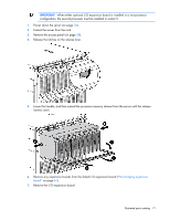
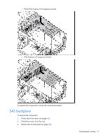
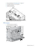
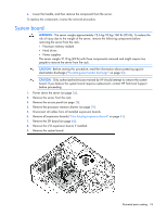
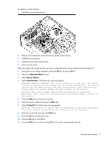
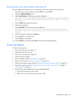
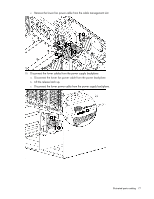
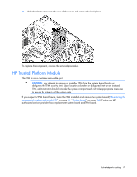
Re-entering the server serial number and product ID After you replace the SPI board, you must re-enter the server serial number and the product ID. 1. During the server startup sequence, press the F9 key to access RBSU. 2. Select the Advanced Options menu. 3. Select Serial Number. The following warning is displayed: Warning: The serial number should ONLY be modified by qualified service personnel. This value should always match the serial number located on the chassis. 4. Press the Enter key to clear the warning. 5. Enter the serial number. 6. Select Product ID. The following warning is displayed: Warning: The Product ID should ONLY be modified by qualified service personnel. This value should always match the Product ID located on the chassis. 7. Enter the product ID, and press the Enter key. 8. Press the Esc key to close the menu. 9. Press the Esc key to exit RBSU. 10. Press the F10 key to confirm exiting RBSU. The server automatically reboots. Power backplane To remove the component: 1. Power down the server (on page 26). 2. Extend the server from the rack. 3. Remove the access panel (on page 28). 4. Remove all power supplies. 5. Remove the XNC module. ("XNC module" on page 73) 6. Remove the SPI board ("SPI board components" on page 98). 7. Remove the processor memory drawers. ("Remove the processor memory drawer" on page 29) 8. Remove the system board ("Re-entering the server serial number and product ID" on page 76, "System board" on page 74). 9. Disconnect the upper cables from the power supply backplane. a. Disconnect the upper fan power cable. b. Remove the screws and disconnect the power cable. Illustrated parts catalog 76
-
 1
1 -
2
-
3
-
4
-
5
-
6
-
7
-
8
-
9
-
10
-
11
-
12
-
13
-
14
-
15
-
16
-
17
-
18
-
19
-
20
-
21
-
22
-
23
-
24
-
25
-
26
-
27
-
28
-
29
-
30
-
31
-
32
-
33
-
34
-
35
-
36
-
37
-
38
-
39
-
40
-
41
-
42
-
43
-
44
-
45
-
46
-
47
-
48
-
49
-
50
-
51
-
52
-
53
-
54
-
55
-
56
-
57
-
58
-
59
-
60
-
61
-
62
-
63
-
64
-
65
-
66
-
67
-
68
-
69
-
70
-
 71
71 -
 72
72 -
 73
73 -
 74
74 -
 75
75 -
 76
76 -
 77
77 -
 78
78 -
 79
79 -
 80
80 -
 81
81 -
82
-
83
-
84
-
85
-
86
-
87
-
88
-
89
-
90
-
91
-
92
-
93
-
94
-
95
-
96
-
97
-
98
-
99
-
100
-
101
-
102
-
103
-
104
-
105
-
106
-
107
-
108
-
109
-
110
-
111
-
112
 |
 |