HP ProLiant DL980 DL980 G7 Maintenance & Service Guide - Page 66
Remove the SPI board, Systems Insight Display assembly
 |
View all HP ProLiant DL980 manuals
Add to My Manuals
Save this manual to your list of manuals |
Page 66 highlights
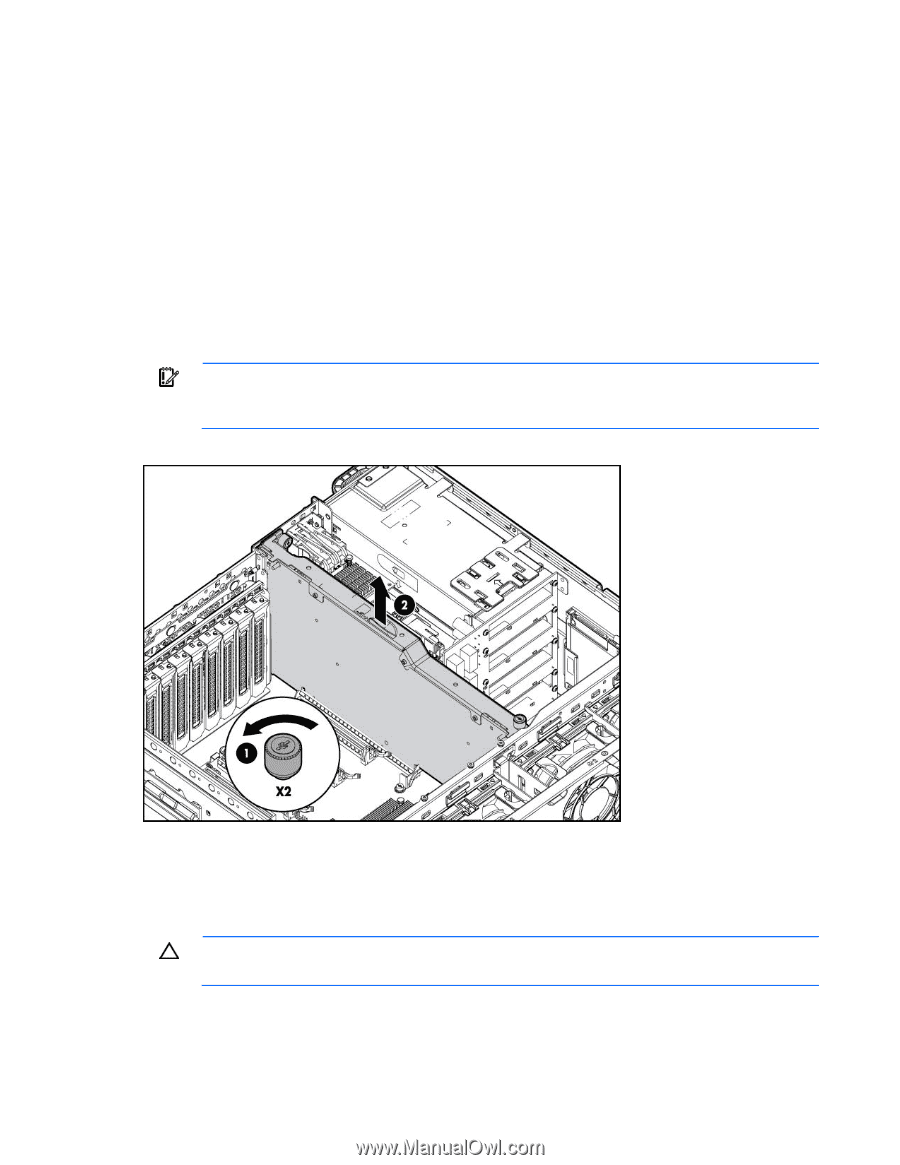
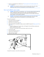
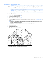
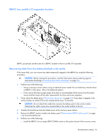
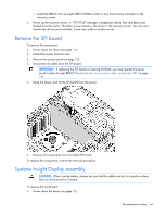
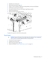
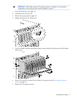
o Install the BBWC into an empty BBWC DIMM socket on any Smart Array Controller in the recovery server. 6. Power up the recovery server. A 1759 POST message is displayed, stating that valid data was flushed from the cache. This data is now stored on the drives in the recovery server. You can now transfer the drives (and controller, if one was used) to another server. Remove the SPI board To remove the component: 1. Power down the server (on page 26). 2. Extend the server from the rack. 3. Remove the access panel (on page 28). 4. Disconnect all cables from the SPI board. IMPORTANT: If replacing the SPI board or clearing NVRAM, you must re-enter the server serial number through RBSU ("Re-entering the server serial number and product ID" on page 76). 5. Raise the levers, and lift the SPI board from the server. 6. Remove all components from the failed SPI board. To replace the component, reverse the removal procedure. Systems Insight Display assembly CAUTION: When routing cables, always be sure that the cables are not in a position where they can be pinched or crimped. To remove the component: 1. Power down the server (on page 26). Illustrated parts catalog 66
-
 1
1 -
2
-
3
-
4
-
5
-
6
-
7
-
8
-
9
-
10
-
11
-
12
-
13
-
14
-
15
-
16
-
17
-
18
-
19
-
20
-
21
-
22
-
23
-
24
-
25
-
26
-
27
-
28
-
29
-
30
-
31
-
32
-
33
-
34
-
35
-
36
-
37
-
38
-
39
-
40
-
41
-
42
-
43
-
44
-
45
-
46
-
47
-
48
-
49
-
50
-
51
-
52
-
53
-
54
-
55
-
56
-
57
-
58
-
59
-
60
-
 61
61 -
 62
62 -
 63
63 -
 64
64 -
 65
65 -
 66
66 -
 67
67 -
 68
68 -
 69
69 -
 70
70 -
 71
71 -
72
-
73
-
74
-
75
-
76
-
77
-
78
-
79
-
80
-
81
-
82
-
83
-
84
-
85
-
86
-
87
-
88
-
89
-
90
-
91
-
92
-
93
-
94
-
95
-
96
-
97
-
98
-
99
-
100
-
101
-
102
-
103
-
104
-
105
-
106
-
107
-
108
-
109
-
110
-
111
-
112
 |
 |