HP Tc2100 hp server tc2100 installation sheet (English) - Page 13
Controls, Ports, and Indicators, Introduction, Front Panel
 |
View all HP Tc2100 manuals
Add to My Manuals
Save this manual to your list of manuals |
Page 13 highlights
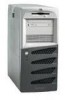
2 Controls, Ports, and Indicators Introduction Before operating the HP Tower Server tc2100, familiarize yourself with the HP Server's controls, ports, and indicators, as shown in Figures 2-1 through 2-3. Front Panel The front panel of the HP Server tc2100 provides the controls and indicators commonly used when operating the Server. Power On/Off/ Sleep LED Power On/Off/ Sleep Switch IDE/SCSI Device Activity LED LAN Activity LED Flexible Disk Drive (FDD) CD-ROM Drive Backup Tape Drive (Optional) 3rd Hard Drive (Optional) Rubber Feet (4) Figure 2-1. Front Panel Table 2-1 provides the front panel power switch and the lower bezel LED indicator definitions. 7
-
 1
1 -
2
-
3
-
4
-
5
-
6
-
7
-
 8
8 -
 9
9 -
 10
10 -
 11
11 -
 12
12 -
 13
13 -
 14
14 -
 15
15 -
 16
16 -
 17
17 -
 18
18 -
19
-
20
-
21
-
22
-
23
-
24
-
25
-
26
-
27
-
28
-
29
-
30
-
31
-
32
-
33
-
34
-
35
-
36
-
37
-
38
-
39
-
40
-
41
-
42
-
43
-
44
-
45
-
46
-
47
-
48
-
49
-
50
-
51
-
52
-
53
-
54
-
55
-
56
-
57
-
58
-
59
-
60
-
61
-
62
-
63
-
64
-
65
-
66
-
67
-
68
-
69
-
70
-
71
-
72
-
73
-
74
-
75
-
76
-
77
-
78
-
79
-
80
-
81
-
82
-
83
-
84
-
85
-
86
-
87
-
88
-
89
-
90
-
91
-
92
-
93
-
94
-
95
-
96
-
97
-
98
-
99
-
100
-
101
-
102
-
103
-
104
-
105
-
106
-
107
 |
 |

7
2
Controls, Ports, and Indicators
Introduction
Before operating the HP Tower Server tc2100, familiarize yourself with the HP
Server's controls, ports, and indicators, as shown in Figures 2-1 through 2-3.
Front Panel
The front panel of the HP Server tc2100 provides the controls and indicators
commonly used when operating the Server.
Flexible Disk
Drive (FDD)
Backup Tape
Drive (Optional)
3rd Hard Drive
(Optional)
CD-ROM Drive
Power On/Off/
Sleep Switch
Power On/Off/
Sleep LED
IDE/SCSI
Device
Activity LED
Rubber Feet (4)
LAN Activity
LED
Figure 2-1. Front Panel
Table 2-1 provides the front panel power switch and the lower bezel LED
indicator definitions.