HP Tc2100 hp server tc2100 installation sheet (English) - Page 23
Opening and Closing the HP Server, Introduction, Tools Required, Removing the Covers
 |
View all HP Tc2100 manuals
Add to My Manuals
Save this manual to your list of manuals |
Page 23 highlights
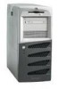
3 Opening and Closing the HP Server Introduction This chapter describes how to remove and replace the HP Tower Server tc2100's left side cover and the upper front bezel. WARNING Before removing the cover, always disconnect the power cord and unplug telephone cables. Disconnect the power cord to avoid exposure to high energy levels that may cause burns when parts are short-circuited by metal objects such as tools or jewelry. Disconnect telephone cables to avoid exposure to shock hazard from telephone ringing voltages. Tools Required No tools are required when removing the basic covers of the HP Server, or accessing the internal components of the Server. Removing the Covers The side cover and the upper front bezel are the only two covers described in this chapter. For more information about removing the Server's remaining covers and bezel, refer to the HP Server tc2100 Service Guide. • The left side cover (front view) must be removed to access the internal components of the Server. • The left side cover must be removed before removing the front bezel. • The upper front bezel must be removed to access the mass storage devices in the upper four shelves (first four drive shelves or common trays). NOTE You do not need to remove the upper front bezel of the HP Server tc2100 to install internal accessories, such as memory, PCI accessory boards, or internal mass storage devices. However, you must remove the upper front bezel to access the mass storage devices in the front of the Server. 17
-
 1
1 -
2
-
3
-
4
-
5
-
6
-
7
-
8
-
9
-
10
-
11
-
12
-
13
-
14
-
15
-
16
-
17
-
 18
18 -
 19
19 -
 20
20 -
 21
21 -
 22
22 -
 23
23 -
 24
24 -
 25
25 -
 26
26 -
 27
27 -
 28
28 -
29
-
30
-
31
-
32
-
33
-
34
-
35
-
36
-
37
-
38
-
39
-
40
-
41
-
42
-
43
-
44
-
45
-
46
-
47
-
48
-
49
-
50
-
51
-
52
-
53
-
54
-
55
-
56
-
57
-
58
-
59
-
60
-
61
-
62
-
63
-
64
-
65
-
66
-
67
-
68
-
69
-
70
-
71
-
72
-
73
-
74
-
75
-
76
-
77
-
78
-
79
-
80
-
81
-
82
-
83
-
84
-
85
-
86
-
87
-
88
-
89
-
90
-
91
-
92
-
93
-
94
-
95
-
96
-
97
-
98
-
99
-
100
-
101
-
102
-
103
-
104
-
105
-
106
-
107
 |
 |
