HP rp7405 User Guide, Third Edition - hp rp7405/rp7410 Servers - Page 129
Raised Floor Grounding, Appendix C, Grounding Systems
 |
View all HP rp7405 manuals
Add to My Manuals
Save this manual to your list of manuals |
Page 129 highlights
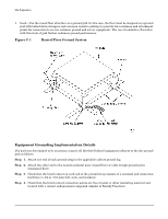
Site Preparation Grounding Systems NOTE In some cases power distribution system green (green/yellow) wire ground conductors are too long and inductive to provide adequate high frequency ground return paths. Therefore, the server is shipped with a ground strap for connecting the system cabinet to the site grounding grid (customer-supplied). When connecting this ground, ensure that the raised floor is properly grounded. Power panels located in close proximity to the computer equipment should also be connected to the site grounding grid. Methods of providing a sufficiently high frequency ground grid are described in the next sections. Raised Floor Grounding If a raised floor system is used, install a complete signal grounding grid for maintaining equal potential over a broad band of frequencies. The grounding grid should be connected to the equipment cabinet and electrical service entrance ground at multiple connection points using a minimum #6 AWG (16mm2) wire ground conductor. Hewlett-Packard recommends the following approaches: • Excellent-Add a grounding grid to the subfloor. The grounding grid should be made of aluminum strips mounted to the subfloor. The strips should be 0.032 in. (0.08 cm) thick and a minimum of 3.0 in. (8.0 cm) wide. Connect each pedestal to four strips using 1/4 in. (6.0 mm) bolts tightened to the manufacturer's torque recommendation. Appendix C 107
-
 1
1 -
2
-
3
-
4
-
5
-
6
-
7
-
8
-
9
-
10
-
11
-
12
-
13
-
14
-
15
-
16
-
17
-
18
-
19
-
20
-
21
-
22
-
23
-
24
-
25
-
26
-
27
-
28
-
29
-
30
-
31
-
32
-
33
-
34
-
35
-
36
-
37
-
38
-
39
-
40
-
41
-
42
-
43
-
44
-
45
-
46
-
47
-
48
-
49
-
50
-
51
-
52
-
53
-
54
-
55
-
56
-
57
-
58
-
59
-
60
-
61
-
62
-
63
-
64
-
65
-
66
-
67
-
68
-
69
-
70
-
71
-
72
-
73
-
74
-
75
-
76
-
77
-
78
-
79
-
80
-
81
-
82
-
83
-
84
-
85
-
86
-
87
-
88
-
89
-
90
-
91
-
92
-
93
-
94
-
95
-
96
-
97
-
98
-
99
-
100
-
101
-
102
-
103
-
104
-
105
-
106
-
107
-
108
-
109
-
110
-
111
-
112
-
113
-
114
-
115
-
116
-
117
-
118
-
119
-
120
-
121
-
122
-
123
-
 124
124 -
 125
125 -
 126
126 -
 127
127 -
 128
128 -
 129
129 -
 130
130 -
 131
131 -
 132
132 -
 133
133 -
 134
134 -
135
-
136
-
137
-
138
-
139
-
140
-
141
-
142
-
143
-
144
-
145
-
146
 |
 |
