HP rp7405 User Guide, Third Edition - hp rp7405/rp7410 Servers - Page 76
OL* LEDs, <TABLE>, PCI/Cell LED OL*, MP Core I/O LEDs, Location, Driven By, State, Description, Power
 |
View all HP rp7405 manuals
Add to My Manuals
Save this manual to your list of manuals |
Page 76 highlights
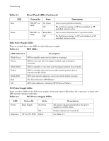
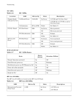
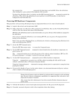
Troubleshooting Common Installation Problems OL* LEDs Table 3-6 OL* LEDs Location LED Chassis Beside Cell Board Power Cell and On Cell Driven By State Cell LPM On Green PCI OL* Board MP Core I/O Panel Cell Attention PCI Slot Power SP via GPM LBA PCI Slot Attention LBA PCI Slot Power LBA PCI Slot Attention LBA Yellow On Green Off Off Yellow On Green Off Off Yellow Description 3.3V SB and Cell_Pwr_Good 3.3V SB off, or 3.3V SB on and no Cell_Pwr_Good See Table 3-7. Slot is powered Slot is not powered Normal See Table 3-7. Core is powered Core is not powered Normal See Table 3-7. PCI/Cell LED OL* Table 3-7 OL* LEDs States State Power (Green) Normal Operation (powered) On Fault Detected, power on On Slot Selected, power on, NOT Ready for OL* On Power off or Slot Available Off Fault Detected, power off Off Ready for OL* Off Attention (Yellow) Off Flashing On Off Flashing On MP Core I/O LEDs The MP Core I/O LEDs are located on the MP Core I/O Panel. Table 3-8 MP Core I/O LEDs LED Management Processor Power Good Driven By 3.3SB State On Green Off Description 3.3V SB is on 3.3V SB off 54 Chapter 3
-
 1
1 -
2
-
3
-
4
-
5
-
6
-
7
-
8
-
9
-
10
-
11
-
12
-
13
-
14
-
15
-
16
-
17
-
18
-
19
-
20
-
21
-
22
-
23
-
24
-
25
-
26
-
27
-
28
-
29
-
30
-
31
-
32
-
33
-
34
-
35
-
36
-
37
-
38
-
39
-
40
-
41
-
42
-
43
-
44
-
45
-
46
-
47
-
48
-
49
-
50
-
51
-
52
-
53
-
54
-
55
-
56
-
57
-
58
-
59
-
60
-
61
-
62
-
63
-
64
-
65
-
66
-
67
-
68
-
69
-
70
-
 71
71 -
 72
72 -
 73
73 -
 74
74 -
 75
75 -
 76
76 -
 77
77 -
 78
78 -
 79
79 -
 80
80 -
 81
81 -
82
-
83
-
84
-
85
-
86
-
87
-
88
-
89
-
90
-
91
-
92
-
93
-
94
-
95
-
96
-
97
-
98
-
99
-
100
-
101
-
102
-
103
-
104
-
105
-
106
-
107
-
108
-
109
-
110
-
111
-
112
-
113
-
114
-
115
-
116
-
117
-
118
-
119
-
120
-
121
-
122
-
123
-
124
-
125
-
126
-
127
-
128
-
129
-
130
-
131
-
132
-
133
-
134
-
135
-
136
-
137
-
138
-
139
-
140
-
141
-
142
-
143
-
144
-
145
-
146
 |
 |
