IBM 8658 User Guide - Page 133
Removing, system, board
 |
UPC - 087944602644
View all IBM 8658 manuals
Add to My Manuals
Save this manual to your list of manuals |
Page 133 highlights
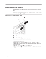
1 Tab 2 Power supply backplane To remove the power supply backplane: 1. Power off the server. 2. Disconnect all external cables from the server. 3. Remove the cover. See "Removing the cover, door, and bezel" on page 48. 4. Disconnect cables from the backplane. 5. Press the arrow on the tab 1 to release the backplane. 6. Slide out the power supply backplane 2 to remove. Removing the system board 1 Screws (9) 2 System Board To remove the system board: 1. Power off the server. 2. Disconnect all external cables from the server. 3. Remove the cover. See "Removing the cover, door, and bezel" on page 48. 4. Remove the rear air flow fan. See "Replacing a fan assembly" on page 69. 5. Remove the DASD backplane assembly. See ″"Removing the DASD backplane assembly" on page 122.″ 6. Remove the power supply backplane. See ″"Removing the power supply backplane" on page 122.″ 7. Disconnect the system board cables. 8. Remove the screws (9) 1 . 9. Gently pull out the system board 2 to remove. FRU information (service only) 123
-
 1
1 -
2
-
3
-
4
-
5
-
6
-
7
-
8
-
9
-
10
-
11
-
12
-
13
-
14
-
15
-
16
-
17
-
18
-
19
-
20
-
21
-
22
-
23
-
24
-
25
-
26
-
27
-
28
-
29
-
30
-
31
-
32
-
33
-
34
-
35
-
36
-
37
-
38
-
39
-
40
-
41
-
42
-
43
-
44
-
45
-
46
-
47
-
48
-
49
-
50
-
51
-
52
-
53
-
54
-
55
-
56
-
57
-
58
-
59
-
60
-
61
-
62
-
63
-
64
-
65
-
66
-
67
-
68
-
69
-
70
-
71
-
72
-
73
-
74
-
75
-
76
-
77
-
78
-
79
-
80
-
81
-
82
-
83
-
84
-
85
-
86
-
87
-
88
-
89
-
90
-
91
-
92
-
93
-
94
-
95
-
96
-
97
-
98
-
99
-
100
-
101
-
102
-
103
-
104
-
105
-
106
-
107
-
108
-
109
-
110
-
111
-
112
-
113
-
114
-
115
-
116
-
117
-
118
-
119
-
120
-
121
-
122
-
123
-
124
-
125
-
126
-
127
-
 128
128 -
 129
129 -
 130
130 -
 131
131 -
 132
132 -
 133
133 -
 134
134 -
 135
135 -
 136
136 -
 137
137 -
 138
138 -
139
-
140
-
141
-
142
-
143
-
144
-
145
-
146
-
147
-
148
-
149
-
150
-
151
-
152
-
153
-
154
-
155
-
156
-
157
-
158
-
159
-
160
-
161
-
162
-
163
-
164
-
165
-
166
-
167
-
168
-
169
-
170
-
171
-
172
-
173
-
174
-
175
-
176
-
177
-
178
-
179
-
180
-
181
-
182
-
183
-
184
-
185
-
186
-
187
-
188
-
189
-
190
-
191
-
192
-
193
-
194
-
195
-
196
-
197
-
198
-
199
-
200
 |
 |
