IBM 8658 User Guide - Page 25
Diagnostic, programs, error, messages
 |
UPC - 087944602644
View all IBM 8658 manuals
Add to My Manuals
Save this manual to your list of manuals |
Page 25 highlights
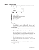
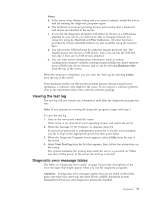
identifying problems using these LEDs. PS1 PS2 PS3 NON OVER NMI TEMP FAN MEM CPU PCI A PCI B VRM DASD1 DASD2 Light path diagnostics table The System Error LED on the operator information panel is lit when certain system errors occur. If the System Error LED on your server is lit, use the table in "Information panel system error LED" on page 128 to help determine the cause of the error and the action you should take. Diagnostic programs and error messages The server diagnostic programs are stored in upgradable read-only memory (ROM) on the system board. These programs are the primary method of testing the major components of your server. Diagnostic error messages indicate that a problem exists; they are not intended to be used to identify a failing part. Sometimes the first error to occur causes additional errors. In this case, the server displays more than one error message. Always follow the suggested action instructions for the first error message that appears. The following sections contain the error codes that might appear in the detailed test log and summary log when running the diagnostic programs. The error code format is as follows: fff-ttt-iii-date-cc-text message where: fff is the three-digit function code that indicates the function being tested when the error occurred. For example, function code 089 is for the microprocessor. ttt is the three-digit failure code that indicates the exact test failure that was encountered. Diagnostics 15
-
 1
1 -
2
-
3
-
4
-
5
-
6
-
7
-
8
-
9
-
10
-
11
-
12
-
13
-
14
-
15
-
16
-
17
-
18
-
19
-
 20
20 -
 21
21 -
 22
22 -
 23
23 -
 24
24 -
 25
25 -
 26
26 -
 27
27 -
 28
28 -
 29
29 -
 30
30 -
31
-
32
-
33
-
34
-
35
-
36
-
37
-
38
-
39
-
40
-
41
-
42
-
43
-
44
-
45
-
46
-
47
-
48
-
49
-
50
-
51
-
52
-
53
-
54
-
55
-
56
-
57
-
58
-
59
-
60
-
61
-
62
-
63
-
64
-
65
-
66
-
67
-
68
-
69
-
70
-
71
-
72
-
73
-
74
-
75
-
76
-
77
-
78
-
79
-
80
-
81
-
82
-
83
-
84
-
85
-
86
-
87
-
88
-
89
-
90
-
91
-
92
-
93
-
94
-
95
-
96
-
97
-
98
-
99
-
100
-
101
-
102
-
103
-
104
-
105
-
106
-
107
-
108
-
109
-
110
-
111
-
112
-
113
-
114
-
115
-
116
-
117
-
118
-
119
-
120
-
121
-
122
-
123
-
124
-
125
-
126
-
127
-
128
-
129
-
130
-
131
-
132
-
133
-
134
-
135
-
136
-
137
-
138
-
139
-
140
-
141
-
142
-
143
-
144
-
145
-
146
-
147
-
148
-
149
-
150
-
151
-
152
-
153
-
154
-
155
-
156
-
157
-
158
-
159
-
160
-
161
-
162
-
163
-
164
-
165
-
166
-
167
-
168
-
169
-
170
-
171
-
172
-
173
-
174
-
175
-
176
-
177
-
178
-
179
-
180
-
181
-
182
-
183
-
184
-
185
-
186
-
187
-
188
-
189
-
190
-
191
-
192
-
193
-
194
-
195
-
196
-
197
-
198
-
199
-
200
 |
 |
