IBM IC35L020 Hard Drive Specifications - Page 39
Specification, Electrical interface
 |
View all IBM IC35L020 manuals
Add to My Manuals
Save this manual to your list of manuals |
Page 39 highlights
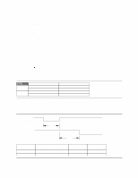
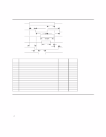
9.0 Specification 9.1 Electrical interface 9.1.1 Connector location Refer to the following illustration to see the location of the connectors. Figure 19. Connector location 9.1.1.1 DC power connector The DC power connector is designed to mate with AMP (P/N 1-480424-0) using AMP pins (P/N 350078-4) (strip) or (P/N 61173-4) (loose piece) or their equivalents. Pin assignments are shown in the following figure. 43 21 Pin Voltage 1 +12 V 2 GND 3 GND 4 +5V Figure 20. Power connector pin assignments 9.1.1.2 AT signal connector The AT signal connector is a 40-pin connector. Deskstar 60 GXP Hard disk drive specification 25
-
 1
1 -
2
-
3
-
4
-
5
-
6
-
7
-
8
-
9
-
10
-
11
-
12
-
13
-
14
-
15
-
16
-
17
-
18
-
19
-
20
-
21
-
22
-
23
-
24
-
25
-
26
-
27
-
28
-
29
-
30
-
31
-
32
-
33
-
 34
34 -
 35
35 -
 36
36 -
 37
37 -
 38
38 -
 39
39 -
 40
40 -
 41
41 -
 42
42 -
 43
43 -
 44
44 -
45
-
46
-
47
-
48
-
49
-
50
-
51
-
52
-
53
-
54
-
55
-
56
-
57
-
58
-
59
-
60
-
61
-
62
-
63
-
64
-
65
-
66
-
67
-
68
-
69
-
70
-
71
-
72
-
73
-
74
-
75
-
76
-
77
-
78
-
79
-
80
-
81
-
82
-
83
-
84
-
85
-
86
-
87
-
88
-
89
-
90
-
91
-
92
-
93
-
94
-
95
-
96
-
97
-
98
-
99
-
100
-
101
-
102
-
103
-
104
-
105
-
106
-
107
-
108
-
109
-
110
-
111
-
112
-
113
-
114
-
115
-
116
-
117
-
118
-
119
-
120
-
121
-
122
-
123
-
124
-
125
-
126
-
127
-
128
-
129
-
130
-
131
-
132
-
133
-
134
-
135
-
136
-
137
-
138
-
139
-
140
-
141
-
142
-
143
-
144
-
145
-
146
-
147
-
148
-
149
-
150
-
151
-
152
-
153
-
154
-
155
-
156
-
157
-
158
-
159
-
160
-
161
-
162
-
163
-
164
-
165
-
166
-
167
-
168
-
169
-
170
-
171
-
172
-
173
-
174
-
175
-
176
-
177
-
178
-
179
-
180
-
181
-
182
-
183
-
184
-
185
-
186
-
187
-
188
-
189
-
190
-
191
-
192
-
193
-
194
-
195
-
196
-
197
-
198
-
199
-
200
-
201
-
202
-
203
-
204
-
205
-
206
-
207
-
208
-
209
 |
 |

9.0
Specification
9.1
Electrical interface
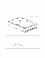
9.1.1
Connector location
Refer to the following illustration to see the location of the connectors.
Figure
19.
Connector location
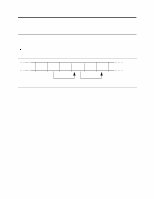
9.1.1.1
DC power connector
The DC power connector is designed to mate with AMP (P/N 1-480424-0) using AMP pins
(P/N 350078-4) (strip) or (P/N 61173-4) (loose piece) or their equivalents.
Pin assignments are shown in
the following figure.
4
3
2
1
Pin
Voltage
1
+12 V
2
GND
3
GND
4
+5V
Figure 20. Power connector pin assignments
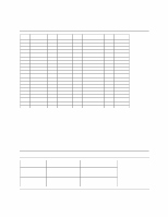
9.1.1.2
AT signal connector
The AT signal connector is a 40-pin connector.
Deskstar
60 GXP Hard disk drive specification
25