IBM IC35L020 Hard Drive Specifications - Page 43
Interface logic signal levels, Reset timings, DDMARDY- Ultra DMA, DSTROBE Ultra DMA, Outputs, Inputs
 |
View all IBM IC35L020 manuals
Add to My Manuals
Save this manual to your list of manuals |
Page 43 highlights
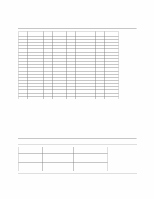
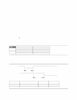
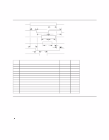
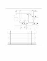
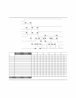
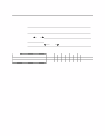
DDMARDY- (Ultra DMA) This signal is used only for Ultra DMA data transfers between the host and the drive. DDMARDY- is a flow control signal for Ultra DMA data out bursts. This signal is held asserted by the device to indicate to the host that the device is ready to receive Ultra DMA data out transfers. The device may negate DDMARDY- to pause an Ultra DMA data out transfer. DSTROBE (Ultra DMA) This signal is used only for Ultra DMA data transfers between the host and the drive. DSTROBE is the data in strobe signal from the device for an Ultra DMA data in transfer. Both the rising and falling edge of DSTROBE latch the data from DD00-DD15 into the host. The device may stop toggling DSTROBE to pause an Ultra DMA data in transfer. Note: The termination resistors at the device side are implemented as follows: Device Termination (implemented on the drive side) O 33 Ω for DD00-DD15, IORDY O 82 Ω for CS0-, CS1-, DA0, DA1, DA2, DIOR-, DIOW-, DMACKO 22 Ω for DMARQ and INTRQ 9.1.3 Interface logic signal levels The interface logic signal has the following electrical specifications: Inputs Outputs Logic level designations Input High Voltage Input Low Voltage Output High Voltage Output Low Voltage Voltage 2.0 (Min.) 0.8 (Max.) 2.4 (Min.) 0.5 (Max.) Figure 23. Interface logic signal level electrical specifications 9.1.4 Reset timings Drive reset timing. RESETt10 BUSY t14 Time duration t10 t14 Parameter description RESET low width RESET high to not BUSY Minimum (s) 25 - Maximum (s) - 31 Figure 24. System reset timing Deskstar 60 GXP Hard disk drive specification 29
-
 1
1 -
2
-
3
-
4
-
5
-
6
-
7
-
8
-
9
-
10
-
11
-
12
-
13
-
14
-
15
-
16
-
17
-
18
-
19
-
20
-
21
-
22
-
23
-
24
-
25
-
26
-
27
-
28
-
29
-
30
-
31
-
32
-
33
-
34
-
35
-
36
-
37
-
 38
38 -
 39
39 -
 40
40 -
 41
41 -
 42
42 -
 43
43 -
 44
44 -
 45
45 -
 46
46 -
 47
47 -
 48
48 -
49
-
50
-
51
-
52
-
53
-
54
-
55
-
56
-
57
-
58
-
59
-
60
-
61
-
62
-
63
-
64
-
65
-
66
-
67
-
68
-
69
-
70
-
71
-
72
-
73
-
74
-
75
-
76
-
77
-
78
-
79
-
80
-
81
-
82
-
83
-
84
-
85
-
86
-
87
-
88
-
89
-
90
-
91
-
92
-
93
-
94
-
95
-
96
-
97
-
98
-
99
-
100
-
101
-
102
-
103
-
104
-
105
-
106
-
107
-
108
-
109
-
110
-
111
-
112
-
113
-
114
-
115
-
116
-
117
-
118
-
119
-
120
-
121
-
122
-
123
-
124
-
125
-
126
-
127
-
128
-
129
-
130
-
131
-
132
-
133
-
134
-
135
-
136
-
137
-
138
-
139
-
140
-
141
-
142
-
143
-
144
-
145
-
146
-
147
-
148
-
149
-
150
-
151
-
152
-
153
-
154
-
155
-
156
-
157
-
158
-
159
-
160
-
161
-
162
-
163
-
164
-
165
-
166
-
167
-
168
-
169
-
170
-
171
-
172
-
173
-
174
-
175
-
176
-
177
-
178
-
179
-
180
-
181
-
182
-
183
-
184
-
185
-
186
-
187
-
188
-
189
-
190
-
191
-
192
-
193
-
194
-
195
-
196
-
197
-
198
-
199
-
200
-
201
-
202
-
203
-
204
-
205
-
206
-
207
-
208
-
209
 |
 |
