IBM IC35L020 Hard Drive Specifications - Page 40
Signal definition, SIGNAL, Read Operation, Conventional Definition, for Ultra DMA
 |
View all IBM IC35L020 manuals
Add to My Manuals
Save this manual to your list of manuals |
Page 40 highlights
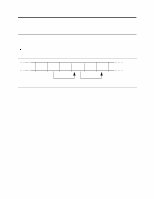
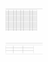
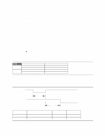
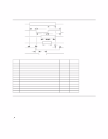
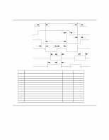
9.1.2 Signal definition The pin assignments of interface signals are listed in the figure below: PIN SIGNAL I/O Type PIN SIGNAL I/O Type 01 RESET- I TTL 02 03 DD7 I/O 3-state 04 05 DD6 I/O 3-state 06 07 DD5 I/O 3-state 08 09 DD4 I/O 3-state 10 11 DD3 I/O 3-state 12 13 DD2 I/O 3-state 14 15 DD1 I/O 3-state 16 17 DD0 I/O 3-state 18 19 GND - - (20) 21 DMARQ O 3-state 22 23 DIOW-(*) I TTL 24 25 DIOR-(*) I TTL 26 27 IORDY(*) O 3-state 28 GND DD8 DD9 DD10 DD11 DD12 DD13 DD14 DD15 key GND GND GND CSEL - - I/O 3-state I/O 3-state I/O 3-state I/O 3-state I/O 3-state I/O 3-state I/O 3-state I/O 3-state - - - - - - - - I TTL 29 DMACK- I TTL 30 GND - - 31 INTRQ O 3-state 32 IOCS16- (**) O OC 33 DA1 I TTL 34 PDIAG- I/O OC 35 DA0 I TTL 36 DA2 I TTL 37 CSO- I TTL 38 CS1- I TTL 39 DASP- I/O OC 40 GND - - Notes: 1. "O" designates an output from the drive. 2. "I" designates an input to the drive. 3. "I/O" designates an input/output common. 4. "OC" designates open-collector or open-drain output. 5. The signal lines marked with (*) are redefined during the Ultra DMA protocol to provide special functions. These lines change from the conventional to special definitions at the moment the Host decides to allow a DMA burst if the Ultra DMA transfer mode was previously chosen via SetFeatures. The Drive becomes aware of this change upon assertion of the DMACK- line. These lines revert back to their original definitions upon the deassertion of DMACK- at the termination of the DMA burst. 6. (**) complies with ATA-2. Figure 21. Table of signal definitions Write Operation Read Operation Special Definition (for Ultra DMA) DDMARDYHSTROBE STOP HDMARDYDSTROBE STOP Figure 22. Special signal definitions for Ultra DMA Conventional Definition IORDY DIORDIOWDIORIORDY DIOW- Deskstar 60 GXP Hard disk drive specification 26
-
 1
1 -
2
-
3
-
4
-
5
-
6
-
7
-
8
-
9
-
10
-
11
-
12
-
13
-
14
-
15
-
16
-
17
-
18
-
19
-
20
-
21
-
22
-
23
-
24
-
25
-
26
-
27
-
28
-
29
-
30
-
31
-
32
-
33
-
34
-
 35
35 -
 36
36 -
 37
37 -
 38
38 -
 39
39 -
 40
40 -
 41
41 -
 42
42 -
 43
43 -
 44
44 -
 45
45 -
46
-
47
-
48
-
49
-
50
-
51
-
52
-
53
-
54
-
55
-
56
-
57
-
58
-
59
-
60
-
61
-
62
-
63
-
64
-
65
-
66
-
67
-
68
-
69
-
70
-
71
-
72
-
73
-
74
-
75
-
76
-
77
-
78
-
79
-
80
-
81
-
82
-
83
-
84
-
85
-
86
-
87
-
88
-
89
-
90
-
91
-
92
-
93
-
94
-
95
-
96
-
97
-
98
-
99
-
100
-
101
-
102
-
103
-
104
-
105
-
106
-
107
-
108
-
109
-
110
-
111
-
112
-
113
-
114
-
115
-
116
-
117
-
118
-
119
-
120
-
121
-
122
-
123
-
124
-
125
-
126
-
127
-
128
-
129
-
130
-
131
-
132
-
133
-
134
-
135
-
136
-
137
-
138
-
139
-
140
-
141
-
142
-
143
-
144
-
145
-
146
-
147
-
148
-
149
-
150
-
151
-
152
-
153
-
154
-
155
-
156
-
157
-
158
-
159
-
160
-
161
-
162
-
163
-
164
-
165
-
166
-
167
-
168
-
169
-
170
-
171
-
172
-
173
-
174
-
175
-
176
-
177
-
178
-
179
-
180
-
181
-
182
-
183
-
184
-
185
-
186
-
187
-
188
-
189
-
190
-
191
-
192
-
193
-
194
-
195
-
196
-
197
-
198
-
199
-
200
-
201
-
202
-
203
-
204
-
205
-
206
-
207
-
208
-
209
 |
 |
