IBM IC35L020 Hard Drive Specifications - Page 44
PIO timings
 |
View all IBM IC35L020 manuals
Add to My Manuals
Save this manual to your list of manuals |
Page 44 highlights
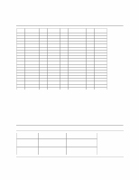
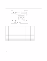
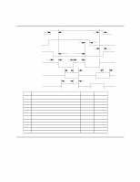
9.1.5 PIO timings The PIO cycle timings meet Mode 4 of the ATA/ATAPI-5 description. CS0-,CS1DA0-2 DIOR-, DIOWWrite data DD00-DD15 Read data DD00-DD15 IOCS16-(*) IORDY t9 t1 t0 t2 t2i t3 t4 t7(*) tA t5 tB t6 t8(*) Parameter descriptions t0 Cycle time t1 CS0- CS1-, DA00-02 valid to DIOR-, DIOW- setup t2 DIOR-, DIOW- pulse width t2i DIOR-, DIOW- recovery time t3 DIOW- data setup t4 DIOW- data hold t5 DIOR- data setup t6 DIOR- data hold t7(*) CS0-, CS1-, DA0-02 valid to IOCS16- assertion t8(*) CS0-, CS1-, DA0-02 invalid to IOCS16- negation t9 DIOR-, DIOW- to CS0-, CS1-, DA0-2 valid hold tA IORDY setup time tB IORDY pulse width (*) Up to ATA-2 (modes-0, 1, and 2) Minimum (ns) 120 25 70 25 20 10 20 5 - - 10 - - Maximum (ns 40 30 35 1250 Figure 25. PIO cycle time 9.1.5.1 Write DRQ interval time For write sectors and write multiple operations, 3.8 us is inserted from the end of negation of the DRQ bit until the setting of the next DRQ bit. 9.1.5.2 Read DRQ interval time For read sectors and read multiple operations the interval from the end of negation of the DRQ bit until the setting of the next DRQ bit is as follows: O If a host reads the status register only before the sector or block transfer, the DRQ interval is 4.2 us. If a host reads the status register after or both before and after the sector or block transfer, the DRQ interval is 11.5 us. Deskstar 60 GXP Hard disk drive specification 30
-
 1
1 -
2
-
3
-
4
-
5
-
6
-
7
-
8
-
9
-
10
-
11
-
12
-
13
-
14
-
15
-
16
-
17
-
18
-
19
-
20
-
21
-
22
-
23
-
24
-
25
-
26
-
27
-
28
-
29
-
30
-
31
-
32
-
33
-
34
-
35
-
36
-
37
-
38
-
 39
39 -
 40
40 -
 41
41 -
 42
42 -
 43
43 -
 44
44 -
 45
45 -
 46
46 -
 47
47 -
 48
48 -
 49
49 -
50
-
51
-
52
-
53
-
54
-
55
-
56
-
57
-
58
-
59
-
60
-
61
-
62
-
63
-
64
-
65
-
66
-
67
-
68
-
69
-
70
-
71
-
72
-
73
-
74
-
75
-
76
-
77
-
78
-
79
-
80
-
81
-
82
-
83
-
84
-
85
-
86
-
87
-
88
-
89
-
90
-
91
-
92
-
93
-
94
-
95
-
96
-
97
-
98
-
99
-
100
-
101
-
102
-
103
-
104
-
105
-
106
-
107
-
108
-
109
-
110
-
111
-
112
-
113
-
114
-
115
-
116
-
117
-
118
-
119
-
120
-
121
-
122
-
123
-
124
-
125
-
126
-
127
-
128
-
129
-
130
-
131
-
132
-
133
-
134
-
135
-
136
-
137
-
138
-
139
-
140
-
141
-
142
-
143
-
144
-
145
-
146
-
147
-
148
-
149
-
150
-
151
-
152
-
153
-
154
-
155
-
156
-
157
-
158
-
159
-
160
-
161
-
162
-
163
-
164
-
165
-
166
-
167
-
168
-
169
-
170
-
171
-
172
-
173
-
174
-
175
-
176
-
177
-
178
-
179
-
180
-
181
-
182
-
183
-
184
-
185
-
186
-
187
-
188
-
189
-
190
-
191
-
192
-
193
-
194
-
195
-
196
-
197
-
198
-
199
-
200
-
201
-
202
-
203
-
204
-
205
-
206
-
207
-
208
-
209
 |
 |
