IBM IC35L020 Hard Drive Specifications - Page 63
Power supply generated ripple at drive power connector, Start up current, Current Amp
 |
View all IBM IC35L020 manuals
Add to My Manuals
Save this manual to your list of manuals |
Page 63 highlights
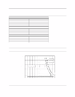
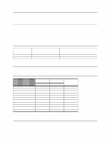
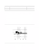
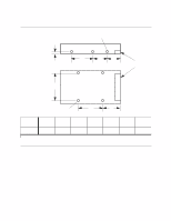
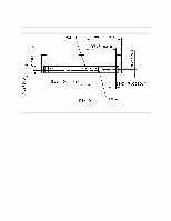
9.3.3 Power supply generated ripple at drive power connector DC Volts (V) +5 +12 Maximum peak-to-peak ripple voltage (mV p-p) 100 150 Frequency range (MHz) 0-10 0-10 Figure 47. Power supply generated ripple at drive power connector During drive start up and seeking a 12-Volt ripple is generated by the drive-this is referred to as dynamic loading. If the power of several drives is daisy chained together, then the power supply ripple plus the dynamic loading of the other drives must remain within the above regulation tolerance. A common supply with separate power leads to each drive is a more desirable method of power distribution. To prevent external electrical noise from interfering with the performance of the drive, the drive must be held in position by four screws in a user's system frame. There must be no electrical level difference at the four screw positions and less than ±300 millivolts peak-to-peak difference level must be maintained between the drive cover and the ground of the drive power connector. 9.3.4 Start up current Since each drive model has the identical spindle motor design, rush currents shorter than 10 us in duration are ignored in the measurement of the start up current of each model. For this reason a single start up current graph represents each of the respective models in this specification. Current (Amp) Time (seconds) DERA004.prz Figure 48. Typical current wave form of the 12 V line at drive start up-listed by drive model capacity Deskstar 60 GXP Hard disk drive specification 49
-
 1
1 -
2
-
3
-
4
-
5
-
6
-
7
-
8
-
9
-
10
-
11
-
12
-
13
-
14
-
15
-
16
-
17
-
18
-
19
-
20
-
21
-
22
-
23
-
24
-
25
-
26
-
27
-
28
-
29
-
30
-
31
-
32
-
33
-
34
-
35
-
36
-
37
-
38
-
39
-
40
-
41
-
42
-
43
-
44
-
45
-
46
-
47
-
48
-
49
-
50
-
51
-
52
-
53
-
54
-
55
-
56
-
57
-
 58
58 -
 59
59 -
 60
60 -
 61
61 -
 62
62 -
 63
63 -
 64
64 -
 65
65 -
 66
66 -
 67
67 -
 68
68 -
69
-
70
-
71
-
72
-
73
-
74
-
75
-
76
-
77
-
78
-
79
-
80
-
81
-
82
-
83
-
84
-
85
-
86
-
87
-
88
-
89
-
90
-
91
-
92
-
93
-
94
-
95
-
96
-
97
-
98
-
99
-
100
-
101
-
102
-
103
-
104
-
105
-
106
-
107
-
108
-
109
-
110
-
111
-
112
-
113
-
114
-
115
-
116
-
117
-
118
-
119
-
120
-
121
-
122
-
123
-
124
-
125
-
126
-
127
-
128
-
129
-
130
-
131
-
132
-
133
-
134
-
135
-
136
-
137
-
138
-
139
-
140
-
141
-
142
-
143
-
144
-
145
-
146
-
147
-
148
-
149
-
150
-
151
-
152
-
153
-
154
-
155
-
156
-
157
-
158
-
159
-
160
-
161
-
162
-
163
-
164
-
165
-
166
-
167
-
168
-
169
-
170
-
171
-
172
-
173
-
174
-
175
-
176
-
177
-
178
-
179
-
180
-
181
-
182
-
183
-
184
-
185
-
186
-
187
-
188
-
189
-
190
-
191
-
192
-
193
-
194
-
195
-
196
-
197
-
198
-
199
-
200
-
201
-
202
-
203
-
204
-
205
-
206
-
207
-
208
-
209
 |
 |
