IBM IC35L020 Hard Drive Specifications - Page 67
Connector and jumper description, 5.4 Drive mounting, 5.5 Head unload and actuator lock
 |
View all IBM IC35L020 manuals
Add to My Manuals
Save this manual to your list of manuals |
Page 67 highlights
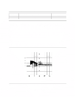
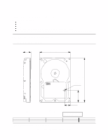
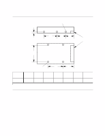
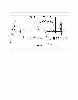
9.5.3 Connector and jumper description Figure 52. Connector and jumper description 9.5.4 Drive mounting The drive will operate in all axes (6 directions). Performance and error rate will stay within specification limits if the drive is operated in the other orientations from which it was formatted. For reliable operation it is recommended that the drive be mounted by using appropriate length side or bottom mounting screws with 6-32 UNC thread count or equivalent mounting hardware. Proper mounting is essential to prevent the drive from excessive motion or vibration during seek operation or spindle rotation. Consult with your IBM Corporation distribution representative if your mounting application may possibly be considered out of compliance with this specification. When performing any drive level vibration and shock test, mount the drive to the table using the bottom four screws. Do not cover the breather hole-illustrated in Figure 50 on page 51-to keep air pressure inside of the disk enclosure equal to the atmospheric pressure outside of the drive enclosure. 9.5.5 Head unload and actuator lock During an unload the heads are moved out from the disks to protect the disk data during shipping, moving, and storage. Upon power down the heads are automatically unloaded from the disk area. The head actuator locking mechanism secures the heads in the unload position. Deskstar 60 GXP Hard disk drive specification 53
-
 1
1 -
2
-
3
-
4
-
5
-
6
-
7
-
8
-
9
-
10
-
11
-
12
-
13
-
14
-
15
-
16
-
17
-
18
-
19
-
20
-
21
-
22
-
23
-
24
-
25
-
26
-
27
-
28
-
29
-
30
-
31
-
32
-
33
-
34
-
35
-
36
-
37
-
38
-
39
-
40
-
41
-
42
-
43
-
44
-
45
-
46
-
47
-
48
-
49
-
50
-
51
-
52
-
53
-
54
-
55
-
56
-
57
-
58
-
59
-
60
-
61
-
 62
62 -
 63
63 -
 64
64 -
 65
65 -
 66
66 -
 67
67 -
 68
68 -
 69
69 -
 70
70 -
 71
71 -
 72
72 -
73
-
74
-
75
-
76
-
77
-
78
-
79
-
80
-
81
-
82
-
83
-
84
-
85
-
86
-
87
-
88
-
89
-
90
-
91
-
92
-
93
-
94
-
95
-
96
-
97
-
98
-
99
-
100
-
101
-
102
-
103
-
104
-
105
-
106
-
107
-
108
-
109
-
110
-
111
-
112
-
113
-
114
-
115
-
116
-
117
-
118
-
119
-
120
-
121
-
122
-
123
-
124
-
125
-
126
-
127
-
128
-
129
-
130
-
131
-
132
-
133
-
134
-
135
-
136
-
137
-
138
-
139
-
140
-
141
-
142
-
143
-
144
-
145
-
146
-
147
-
148
-
149
-
150
-
151
-
152
-
153
-
154
-
155
-
156
-
157
-
158
-
159
-
160
-
161
-
162
-
163
-
164
-
165
-
166
-
167
-
168
-
169
-
170
-
171
-
172
-
173
-
174
-
175
-
176
-
177
-
178
-
179
-
180
-
181
-
182
-
183
-
184
-
185
-
186
-
187
-
188
-
189
-
190
-
191
-
192
-
193
-
194
-
195
-
196
-
197
-
198
-
199
-
200
-
201
-
202
-
203
-
204
-
205
-
206
-
207
-
208
-
209
 |
 |
