IBM x3550 Installation Guide - Page 25
Removing, server, cover
 |
UPC - 883436027151
View all IBM x3550 manuals
Add to My Manuals
Save this manual to your list of manuals |
Page 25 highlights
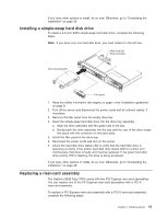
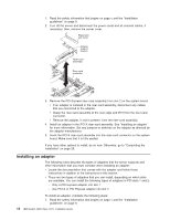
v Do not touch solder joints, pins, or exposed circuitry. v Do not leave the device where others can handle and damage it. v While the device is still in its static-protective package, touch it to an unpainted metal surface on the outside of the server for at least 2 seconds. This drains static electricity from the package and from your body. v Remove the device from its package and install it directly into the server without setting down the device. If it is necessary to set down the device, put it back into its static-protective package. Do not place the device on the server cover or on a metal surface. v Take additional care when handling devices during cold weather. Heating reduces indoor humidity and increases static electricity. Removing the server cover Important: Before you install optional hardware, make sure that the server is working correctly. Start the server, and make sure that the operating system starts, if an operating system is installed, or that a 19990305 error code is displayed, indicating that an operating system was not found but the server is otherwise working correctly. If the server is not working correctly, see the Problem Determination and Service Guide for diagnostic information. To remove the server cover, complete the following steps: 1. Read the safety information that begins on page v and "Installation guidelines" on page 9. 2. If you are planning on removing or installing a microprocessor, memory module, PCI adapter, Remote Supervisor Adapter II SlimLine, RAID controller, simple-swap hard disk drive, or battery, turn off the server and peripheral devices and disconnect the power cords and all external cables, if necessary. Thumbscrew Fan door 3. If the server has been installed in a rack, slide it out from the rack enclosure. See the Rack Installation Instructions that come with the server for information about removing the server from the rack. 4. Slide and lift the two cover-release latches on the fan door on the right side of the top of the server. 5. Lift the fan door cover. 6. Loosen the thumbscrew at the back of the server. 7. Slide the server cover back until the locking tabs release. Chapter 2. Installing options 11
-
 1
1 -
2
-
3
-
4
-
5
-
6
-
7
-
8
-
9
-
10
-
11
-
12
-
13
-
14
-
15
-
16
-
17
-
18
-
19
-
 20
20 -
 21
21 -
 22
22 -
 23
23 -
 24
24 -
 25
25 -
 26
26 -
 27
27 -
 28
28 -
 29
29 -
 30
30 -
31
-
32
-
33
-
34
-
35
-
36
-
37
-
38
-
39
-
40
-
41
-
42
-
43
-
44
-
45
-
46
-
47
-
48
-
49
-
50
-
51
-
52
-
53
-
54
-
55
-
56
-
57
-
58
-
59
-
60
-
61
-
62
-
63
-
64
-
65
-
66
-
67
-
68
-
69
-
70
-
71
-
72
-
73
-
74
-
75
-
76
-
77
-
78
-
79
-
80
-
81
-
82
-
83
-
84
-
85
-
86
-
87
-
88
-
89
-
90
-
91
-
92
-
93
-
94
-
95
-
96
-
97
-
98
-
99
-
100
-
101
-
102
 |
 |
