IBM x3550 Installation Guide - Page 43
Server, controls, connectors, power
 |
UPC - 883436027151
View all IBM x3550 manuals
Add to My Manuals
Save this manual to your list of manuals |
Page 43 highlights
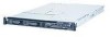
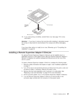
Chapter 3. Server controls, LEDs, connectors, and power This section describes the controls and light-emitting diodes (LEDs) and how to turn the server on and off. Front view The following illustration shows the controls, LEDs, and connectors on the front of the server. This configuration supports up to four 2.5-inch hot-swappable hard disk drives. Rack release latch USB 3 connector USB 4 connector Video connector Operator information panel Rack release latch 2.5-inch hard disk drives Hard disk drive status LED Hard disk drive activity LED CD-RW/DVD eject button CD-RW/DVD drive activity LED The following illustration shows the controls, LEDs, and connectors on the front of the server. This configuration supports up to two 3.5-inch hot-swappable SAS or SATA hard disk drives or two 3.5-inch simple-swap SATA hard disk drives. Rack release latch USB 3 connector USB 4 connector Video connector Operator information panel Rack release latch 3.5-inch hard disk drives CD-RW/DVD eject button CD-RW/DVD drive activity LED Hard disk drive status LED (SAS model) Hard disk drive activity LED (SAS model) Note: The CD-RW/DVD drive is standard in all configurations. The locations of the controls, LEDs, and connectors vary, depending on the hardware configuration that you have. v Operator information panel: This panel contains controls and LEDs about the status of the server. Power-on LED (green) System locator LED (blue) System-error LED (amber) Powercontrol button Hard drive activity LED (green) System information LED (amber) Release latch The following controls and LEDs are on the operator information panel: © Copyright IBM Corp. 2006, 2008 29
-
 1
1 -
2
-
3
-
4
-
5
-
6
-
7
-
8
-
9
-
10
-
11
-
12
-
13
-
14
-
15
-
16
-
17
-
18
-
19
-
20
-
21
-
22
-
23
-
24
-
25
-
26
-
27
-
28
-
29
-
30
-
31
-
32
-
33
-
34
-
35
-
36
-
37
-
 38
38 -
 39
39 -
 40
40 -
 41
41 -
 42
42 -
 43
43 -
 44
44 -
 45
45 -
 46
46 -
 47
47 -
 48
48 -
49
-
50
-
51
-
52
-
53
-
54
-
55
-
56
-
57
-
58
-
59
-
60
-
61
-
62
-
63
-
64
-
65
-
66
-
67
-
68
-
69
-
70
-
71
-
72
-
73
-
74
-
75
-
76
-
77
-
78
-
79
-
80
-
81
-
82
-
83
-
84
-
85
-
86
-
87
-
88
-
89
-
90
-
91
-
92
-
93
-
94
-
95
-
96
-
97
-
98
-
99
-
100
-
101
-
102
 |
 |
