IBM x3550 Installation Guide - Page 83
Diagnosing, problems, using, light, diagnostics, Light - spec
 |
UPC - 883436027151
View all IBM x3550 manuals
Add to My Manuals
Save this manual to your list of manuals |
Page 83 highlights
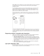
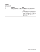
When LEDs are lit to indicate an error, they remain lit when the server is turned off, provided that the server is still connected to power and the power supply is operating correctly. To acknowledge a system error but not take immediate action, press the remind button and place light path diagnostics in remind mode. When the server is in Remind mode, the system-error LED on the front of the server flashes. If a new failure occurs, the system-error LED is lit again. Press the reset button to reset the server and run the power-on self-test (POST). You might have to use a pen or the end of a straightened paper clip to press the button. Light Path Diagnostics REMIND OVER SPEC PS1 PS2 CPU VRM CNFG MEM NMI S ERR SP DASD RAID FAN TEMP BRD PCI The server is designed so that LEDs remain lit when the server is connected to an ac power source but is not turned on, provided that the power supply is operating correctly. This feature helps you to isolate the problem when the operating system is shut down. Diagnosing problems using light path diagnostics LEDs in two locations on the server are available to help you diagnose problems that might occur during installation. Use them in the following order: 1. Light path diagnostics panel - Look at this panel first. If a system error has occurred, the system-error LED on the front of the light path diagnostics drawer is lit. Slide the latch to the left on the front of the light path diagnostics drawer to access the light path diagnostics panel. Note any LEDs that are lit, and then close the drawer. 2. LEDs on the system board - To identify the component that is causing the error, note the lit LED on or beside the component. Light path diagnostics LEDs The following table lists the LEDs on the light path diagnostics panel, the problems that they indicate, and actions to solve the problems. Chapter 5. Solving problems 69
-
 1
1 -
2
-
3
-
4
-
5
-
6
-
7
-
8
-
9
-
10
-
11
-
12
-
13
-
14
-
15
-
16
-
17
-
18
-
19
-
20
-
21
-
22
-
23
-
24
-
25
-
26
-
27
-
28
-
29
-
30
-
31
-
32
-
33
-
34
-
35
-
36
-
37
-
38
-
39
-
40
-
41
-
42
-
43
-
44
-
45
-
46
-
47
-
48
-
49
-
50
-
51
-
52
-
53
-
54
-
55
-
56
-
57
-
58
-
59
-
60
-
61
-
62
-
63
-
64
-
65
-
66
-
67
-
68
-
69
-
70
-
71
-
72
-
73
-
74
-
75
-
76
-
77
-
 78
78 -
 79
79 -
 80
80 -
 81
81 -
 82
82 -
 83
83 -
 84
84 -
 85
85 -
 86
86 -
 87
87 -
 88
88 -
89
-
90
-
91
-
92
-
93
-
94
-
95
-
96
-
97
-
98
-
99
-
100
-
101
-
102
 |
 |
