IBM x3550 Installation Guide - Page 37
User's, Guide, Problem, Determination, Service
 |
UPC - 883436027151
View all IBM x3550 manuals
Add to My Manuals
Save this manual to your list of manuals |
Page 37 highlights
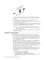
v When you install an additional microprocessor, you must also install one additional cooling fan. See the User's Guide for more information on installing the additional fan. v If you have to replace a microprocessor, call for service. v The microprocessor speeds are automatically set for this server; therefore, you do not have to set any microprocessor frequency-selection jumpers or switches. v If the thermal-grease protective cover (for example, a plastic cap or tape liner) is removed from the heat sink, do not touch the thermal grease on the bottom of the heat sink or set down the heat sink. For details, see the information about thermal grease in the Problem and Determination Service Guide. Note: Removing the heat sink from the microprocessor destroys the even distribution of the thermal grease and requires replacing the thermal grease. Attention: v A startup (boot) microprocessor must always be installed in microprocessor socket 1 on the system board. v To ensure proper server operation when you install an additional microprocessor, use microprocessors that have the same cache size and type, and the same clock speed. Microprocessor internal and external clock frequencies must be identical. v Do not remove the first microprocessor from the system board to install the second microprocessor. The following instructions and illustrations describe how to install the second microprocessor on the system board. To install an additional microprocessor, complete the following steps: 1. Read the safety information that begins on page v and "Installation guidelines" on page 9. 2. Turn off the server and peripheral devices and disconnect the power cords and all external cables, if necessary (see "Turning off the server" on page 32). Remove the server cover. Attention: When you handle static-sensitive devices, take precautions to avoid damage from static electricity. For details about handling these devices, see "Handling static-sensitive devices" on page 10. 3. Locate microprocessor socket 2 on the system board. 4. Remove the microprocessor dust cover from the surface of the microprocessor socket. Chapter 2. Installing options 23
-
 1
1 -
2
-
3
-
4
-
5
-
6
-
7
-
8
-
9
-
10
-
11
-
12
-
13
-
14
-
15
-
16
-
17
-
18
-
19
-
20
-
21
-
22
-
23
-
24
-
25
-
26
-
27
-
28
-
29
-
30
-
31
-
 32
32 -
 33
33 -
 34
34 -
 35
35 -
 36
36 -
 37
37 -
 38
38 -
 39
39 -
 40
40 -
 41
41 -
 42
42 -
43
-
44
-
45
-
46
-
47
-
48
-
49
-
50
-
51
-
52
-
53
-
54
-
55
-
56
-
57
-
58
-
59
-
60
-
61
-
62
-
63
-
64
-
65
-
66
-
67
-
68
-
69
-
70
-
71
-
72
-
73
-
74
-
75
-
76
-
77
-
78
-
79
-
80
-
81
-
82
-
83
-
84
-
85
-
86
-
87
-
88
-
89
-
90
-
91
-
92
-
93
-
94
-
95
-
96
-
97
-
98
-
99
-
100
-
101
-
102
 |
 |
